
Scottiemann goes streetfighter

Rex Kramer-Thrill Seeker
SuperBike
Joined: Jan 2011
Posts: 2,312
From: Brookfield, WI

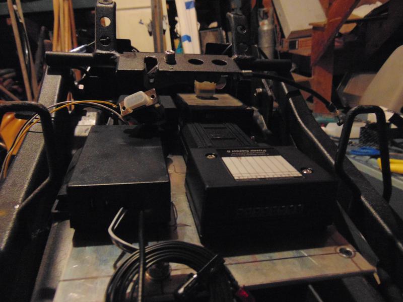
Yea I'm making my own harness, once I'm done with everything I will draw up a wiring diagram for future additions or issues, so I'll post that up. I'm only on step 1 of wiring (component mounting), then I will be working on swapping all the factory connections with weatherpacs, then comes the actual wiring and testing... to be honest I havent even looked into the wiring of the RFID components yet
So did you return it back to stock?
So did you return it back to stock?
Thread Starter
Senior Member
SuperBike
Joined: Feb 2007
Posts: 1,252
From: boston
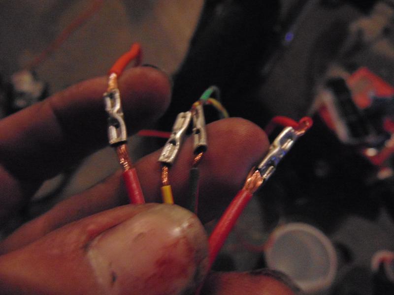
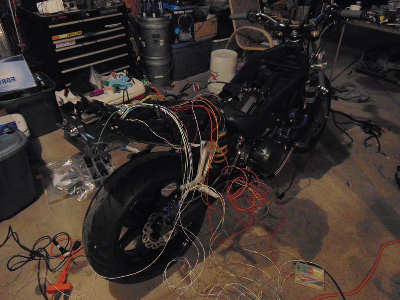
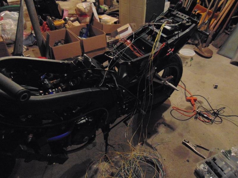
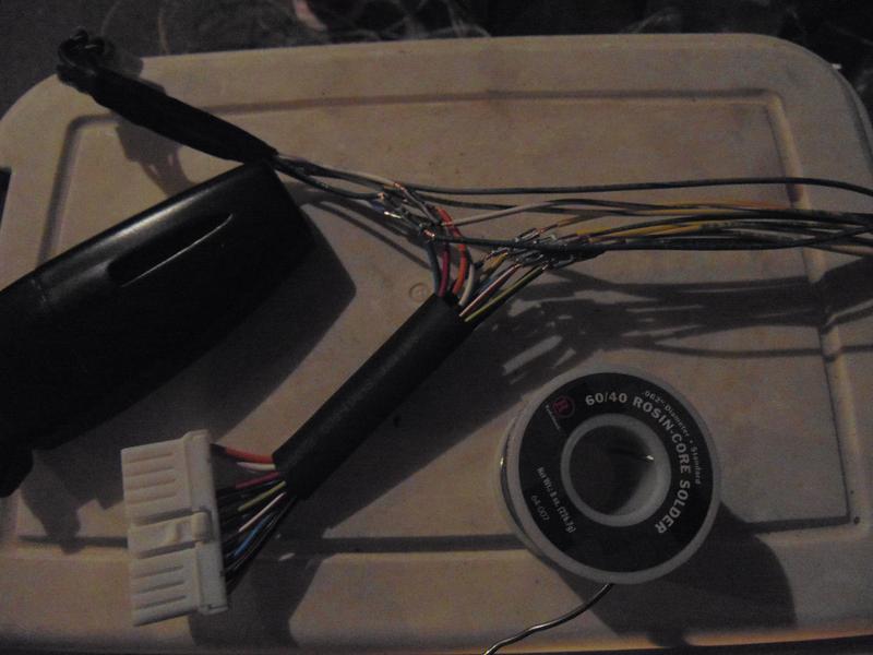
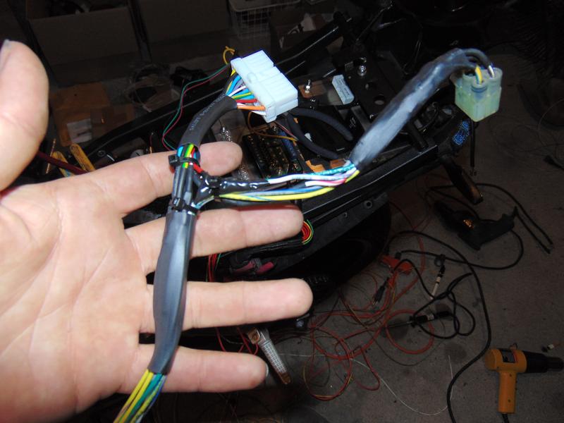
clipping and stripping and crimping and soldering and crimping and plugging and heat shrinking....
I am having so much fun...
I am not having so much fun...
at least I get to sit on my ***
I am having so much fun...
I am not having so much fun...
at least I get to sit on my ***
That one guy
Back Marker
Joined: Jun 2015
Posts: 228
From: Broken Arrow
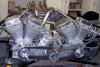
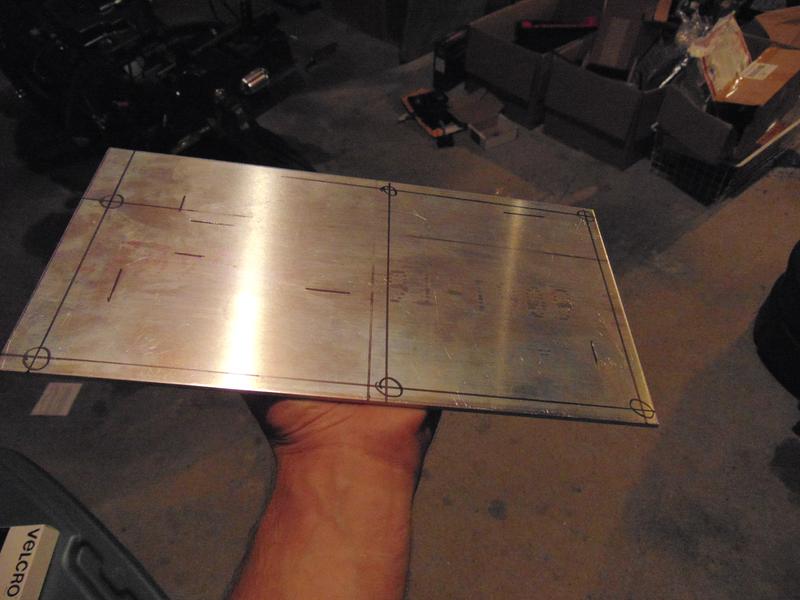
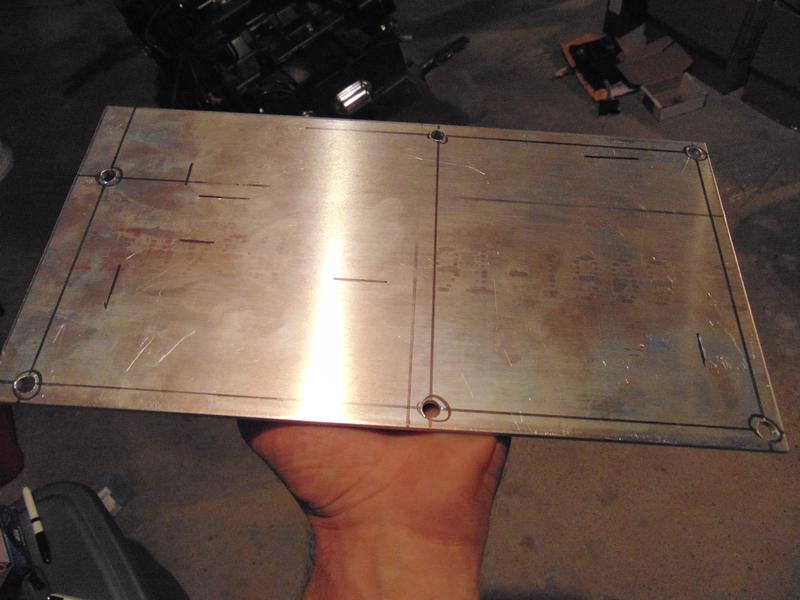
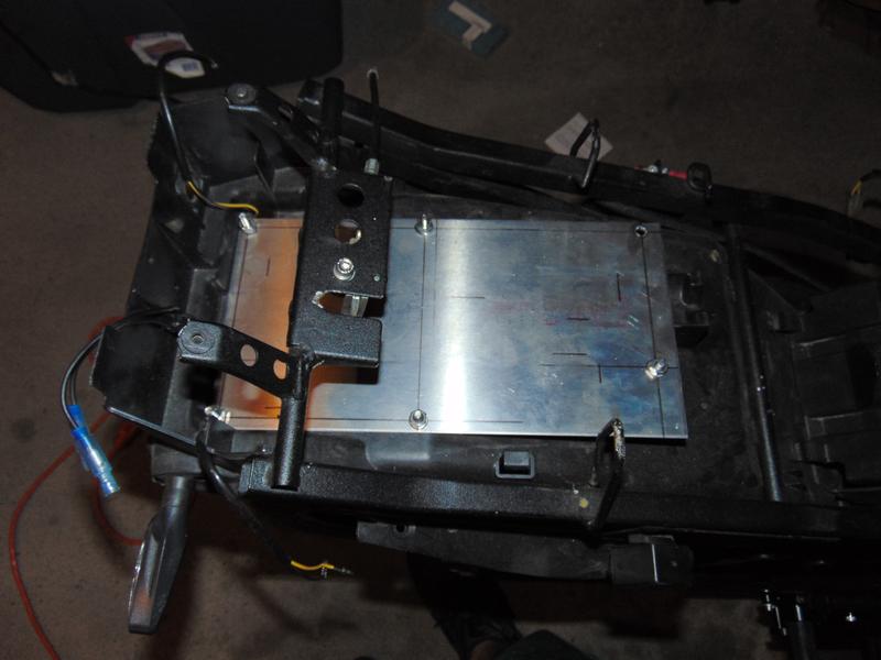
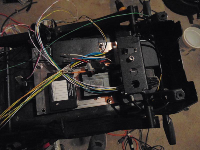
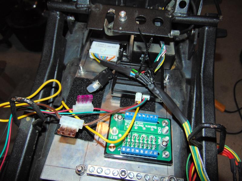
Good God man. I have heard of people having a green thumb but blue and red doesn't seem to suit you. Electrical looks good so far and I like what you did with the plate and components. Keep up the good (hopefully not so bloody) work.
Thread Starter
Senior Member
SuperBike
Joined: Feb 2007
Posts: 1,252
From: boston
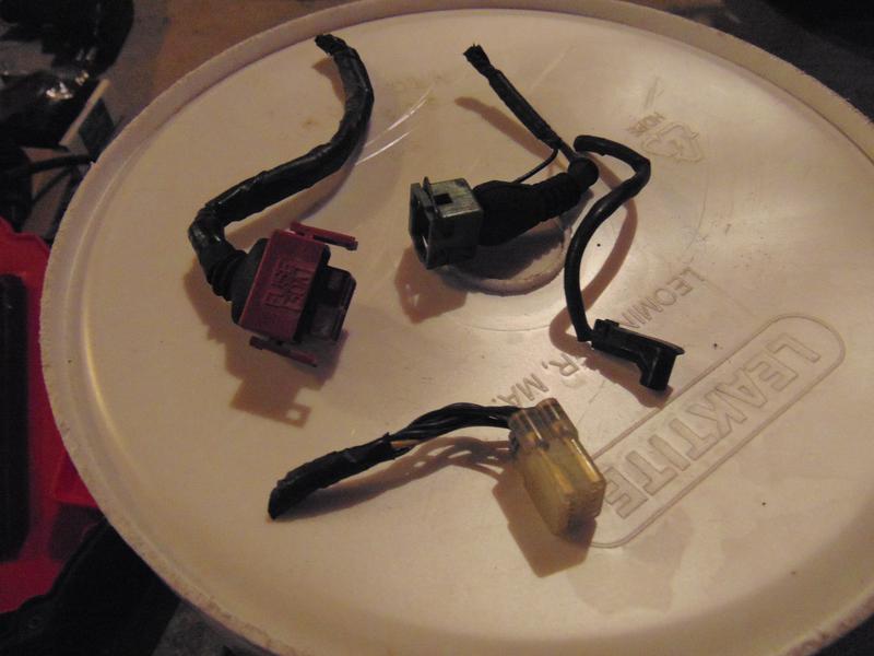
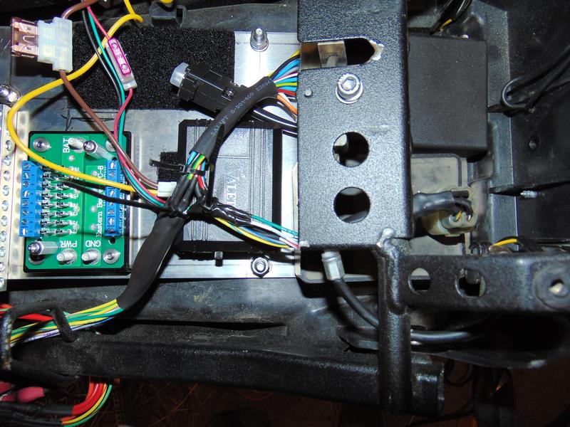
So the only thing that is concerning me is the stock ICU has 13 wires going to it, the ignitech has 11. I just havent had the time to hunt down the pinout for the ignitech to find out whats missing, and the adapter plug on the adapter harness is sealed in a way that i cant see what wire is going to what pin...
Rex Kramer-Thrill Seeker
SuperBike
Joined: Jan 2011
Posts: 2,312
From: Brookfield, WI
So the only thing that is concerning me is the stock ICU has 13 wires going to it, the ignitech has 11. I just havent had the time to hunt down the pinout for the ignitech to find out whats missing, and the adapter plug on the adapter harness is sealed in a way that i cant see what wire is going to what pin...
I wonder if the Ignitech unit does away with the sidestand switch like the HRC ignition unit?
Thread Starter
Senior Member
SuperBike
Joined: Feb 2007
Posts: 1,252
From: boston
hmmmmmm....
so it turns out, the two lines that are left out is pink/white and light green.
The pink/white one goes to the ECT which IIRC is used by the factory ICU to help manage timing advance/retard. Being a programmable unit it makes sense... and there is another temp sensor that goes to the gauges.
And the light green one is for the neutral switch. The starter relay will still utilize the switch and there will be a functioning light at the gauges but the controller dont give a **** lol
Senior Member
SuperBike
Joined: Mar 2012
Posts: 1,544
From: New South Wales Australia
Hey Scottie,
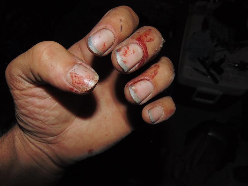
You should rename the build blood sweat and teers!
What a mammoth effort so far.
I wonder what you will do with all your spare time when you finish her?
Go riding I hope!
You should rename the build blood sweat and teers!
What a mammoth effort so far.
I wonder what you will do with all your spare time when you finish her?
Go riding I hope!
Thread Starter
Senior Member
SuperBike
Joined: Feb 2007
Posts: 1,252
From: boston
Oh there has been plenty of blood sweat and tears during this build, well not so many teers, I used to care when I broke things now I just see it as an excersize in creativity 
And yea my deadline to have it done and rideable with no issues is the last weekend in august. The following week I am on vacation and want to ride as much as I can
And yea my deadline to have it done and rideable with no issues is the last weekend in august. The following week I am on vacation and want to ride as much as I can
Thread Starter
Senior Member
SuperBike
Joined: Feb 2007
Posts: 1,252
From: boston
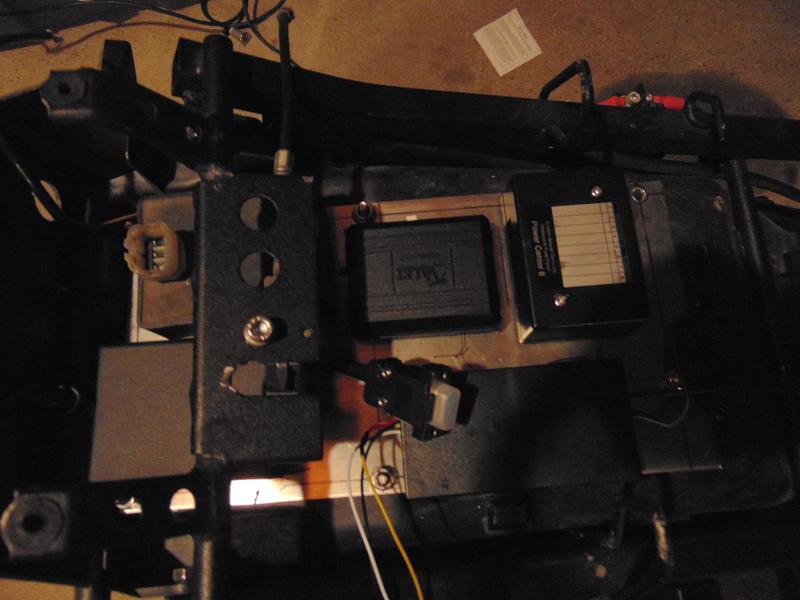
well one project I need to do once this is done is make a detailed, color accurate wiring diagram... A good amount of the wires I'm using dont match factory colors, I am documenting what I'm using against what factory is so hopefully when I'm making all my plugs on the harness side of things I can keep it straight

Senior Member
SuperBike
Joined: Feb 2013
Posts: 1,510
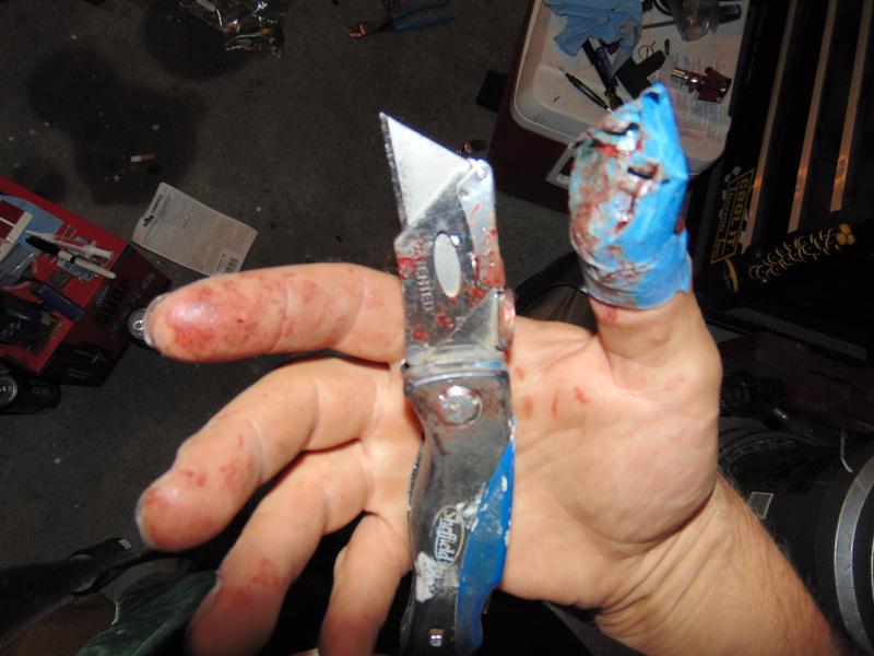
Scottie the Knife!!!
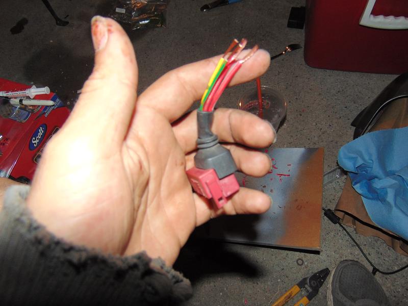
Are you stripping wires wih a utility knife?!!!?? No wire stripper??
Good job on the weather packs! Those should be way better than the stock connections. Man, now i'm tempted to do that this winter too!!!!
James
Are you stripping wires wih a utility knife?!!!?? No wire stripper??
Good job on the weather packs! Those should be way better than the stock connections. Man, now i'm tempted to do that this winter too!!!!
James
Thread Starter
Senior Member
SuperBike
Joined: Feb 2007
Posts: 1,252
From: boston
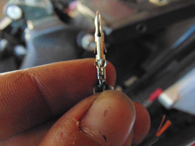
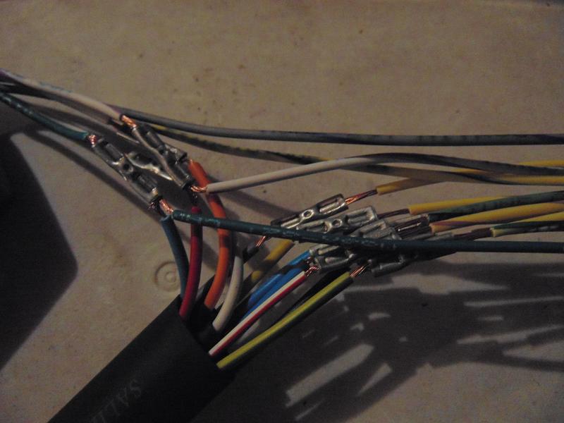
no I was stripping the insulation off of butt crimp teminals because no one stocks uninsulated. Bad technique at first, but after the nice gash I chose a better technique...
dont worry all wires are being stripped, crimped and soldered using the proper tools.
dont worry all wires are being stripped, crimped and soldered using the proper tools.
Thread Starter
Senior Member
SuperBike
Joined: Feb 2007
Posts: 1,252
From: boston
I think I ran into my first wiring issue...
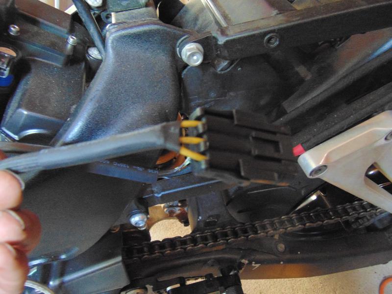
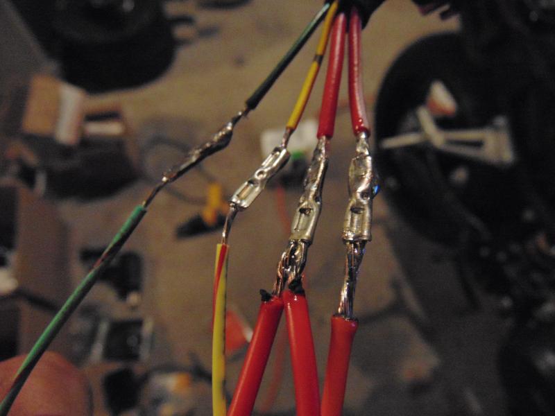
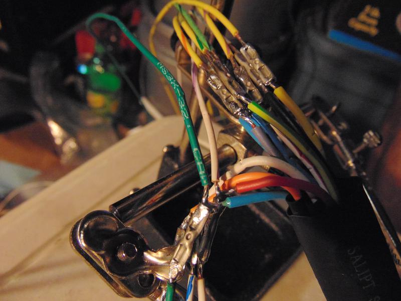
So the stator has 3 solid yellow wires coming from it, while making the weatherpack plug for it I marked the wires with 1,2, and 3 dots with a waterproof lab sharpie and did the same to the factory plug so when I make up the harness side of the plug I can keep them straight.
At one point while making the pins, those marks wore off on the wires so I just finished making the plug and got on with life.
Now I do know automotive electrical fairly well. I am aware that those three wires will send 3 sequential wave signals to the R/R. Once at the R/R the negative gets chopped off and the peaks of those signals will be regulated to make a constant/consistent positive signal.
So my question is, do these actually need to be in any specific order?
From my knowledge of how alternators, stators and R/R's work I'm thinking it doesnt matter as long as each wire sends the same signal by way of a properly functioning stator...
Can anyone confirm?
Senior Member
SuperBike
Joined: Jul 2011
Posts: 1,461
From: South of Live Free or Die & North of Family Guy
Any updates on the wiring?
We got to work on this idea we had on a workable fuel injection Sys' bro', had some more thoughts
We got to work on this idea we had on a workable fuel injection Sys' bro', had some more thoughts
Last edited by NHSH; Aug 11, 2015 at 09:28 PM.

Member
Squid
Joined: Apr 2015
Posts: 79
From: St. Louis MO!


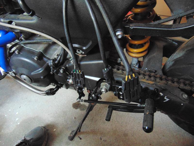
you have them adjusted way back Im assuming...Because mine dont hit at all.
Thread Starter
Senior Member
SuperBike
Joined: Feb 2007
Posts: 1,252
From: boston
Nope, Im an *******
They are adjusted way back and I cant move them forward due to the big *** bolt I fitted for the brake M/C


