
Wiring Plan for my "only track" VTR1000F


Senior Member
SuperSport
SuperSport
Joined: Dec 2006
Posts: 880
From: Victoriaville, Quebec, Canada

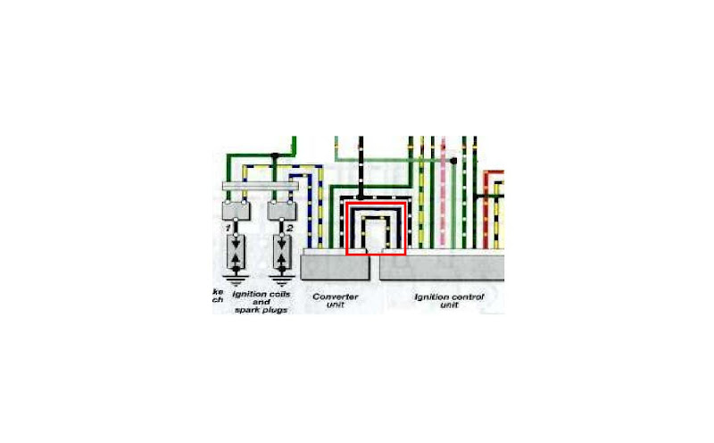
I'll check if you have an AC signal from the ICU to the converter box, if you have the tools.
Or you can test the converter box by scratching (grounding and lifting) the signal wires on the frame, this trigger a bundle of sparks that you can hear cracking even with the plugs on the engine, it would at least split the system in two. You can hook up an alligator clip on the connector and just scratch it, while the converter is powered.
For the tach I was wondering if it was hooked to some RPM gauge, you should see it cranking.
Both coils need to be bolted solidly to the frame
Last edited by gboezio; Jan 4, 2010 at 02:24 AM.
Senior Member
SuperSport
SuperSport
Joined: Dec 2006
Posts: 880
From: Victoriaville, Quebec, Canada
Yes just scratch the wire that goes to the converter removed from the ICU to the frame, it will trigger multiple sparks , or ground and lift, it will make single sparks, if so the converter, coils are working.
One possible thing is that in the rewiring process, you may have inverted the two yellow wires from the pulse generator, this will cause problem, otherwise, I followed the the light green and gr/white wires and I come to the conclusion that they should be grounded as stated before, had to verify to make sure.
Most unlikely, but not out of possibility is that without flywheel the compression is varying the RPM by a wide margin and some pulses may be rejected, cranking without plugs should confirm this, but it has been ran before without flywheel and worked fine.
If it has quitted working, maybe a wire had gone bad.Carefully check the 12V, 3 grounds and pulse gen wires, it should fire without TPS, CTS.
If all fails, get a bottle of wine and find a freind with an ocilloscope
Senior Member
SuperSport
SuperSport
Joined: Dec 2006
Posts: 880
From: Victoriaville, Quebec, Canada
Yes, just remove the ICU connector, put a jumper wire on these wires and scratch the frame or any ground, you should see and hear sparks if the converter and coils work, or if you prefer to use a multimeter, you could get AC voltage between the 12V battery lead and those wires while cranking. Doing this will at least take half the system out of questionning
Is it possible that the yellow and yellow/white from the crank sensor(pulse generator) are reversed during the wiring
And last, are the coils bolted to the frame ?? It's the return path of the spark
Is it possible that the yellow and yellow/white from the crank sensor(pulse generator) are reversed during the wiring
And last, are the coils bolted to the frame ?? It's the return path of the spark
Last edited by gboezio; Jan 6, 2010 at 03:20 PM.

Thread Starter
Senior Member
Back Marker
Joined: Jun 2009
Posts: 125
From: ITALY
I think out of these wires, I should have a 12v signal, and out of converter unit, a AC signal... you do not think?
The wires of pulse generatore are not inverted... and the coils are bolted to the frame.
The wires of pulse generatore are not inverted... and the coils are bolted to the frame.
Senior Member
SuperSport
SuperSport
Joined: Dec 2006
Posts: 880
From: Victoriaville, Quebec, Canada
I know this for sure since it's the way I have installed Microsquirt on the converter

Junior Member
Squid
Joined: May 2012
Posts: 1
I need some help from you
is possible show one of connector with big photo?( I need to know where goes wich color of wire) or write colors of pins one by one
it is 6 pin conector who connects invertor unit.
(123)
(456)
pin positions
My situation is that : I know 1 blue yelow 2 emty (puled out from conector)3 emty (puled out from conector) 4 emty (puled out from conector ) 5 black yelow 6 black blue
I need to know wich pin is black white , green and yelow with smal blue.

Thread
Thread Starter
Forum
Replies
Last Post
j shizzy wizzy
Everything Else
86
Apr 17, 2009 08:27 PM


