
CCT Mod. this is how I did it.


Thread Starter
Member
Squid
Joined: Aug 2012
Posts: 68

CCT Mod. this is how I did it.
BAD IDEA!!
This didn't have the effect your looking for. when the top M6 (screw driver) turns in the Original CCT is reverse thread and turns out! you can play until you get a setting your a happy with and lock it in.. but you can not adjust anything On the bike! this si the major shortcoming of the design.. I'm redo.. I don't recommend this setting after I installed it.
CCT failed.. bent all 4 valves.. have new head ready to go.. but need CCT's..
Read some things here about how to mod.. and this is what I did.
I liked the idea of the set screw in the side of the original CCT. However after drilling and tapping I wasn't as sure.. I had a friend (mechanical eng.) look at it and he said it was fine and would work.. but I'm Paranoid. I wanted something that would compliment the Set screw as the holes were already there.
This is what I came up with.. Put two ideas from the forum together.
here we go..
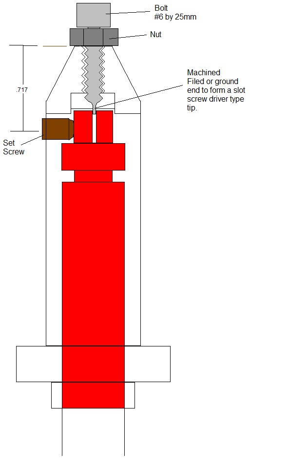
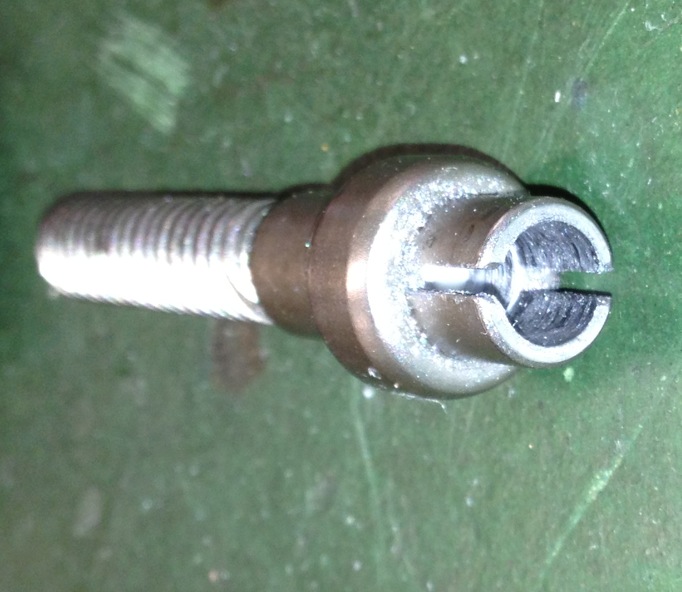
Parts #6 metric bolt 25mm long.. stainless preferred. Grind mill or file the tip until you have a slot screwdriver type tip that fits in the CCT (mine is 1mm wide done on a milling machine) Pick a suitable set screw for the side, I choose 1/4-20 by 1/4 long. I regret this as 20 is a little course.. a 32 or 36 thread count may have been a better choice and you don't need to be as big as 1/4.. so your call here.
Disassemble CCT.. all of it! including the top bolt
Measure .717" from the top of the CCT, mark, center tap and drill with a drill press. then tap (1/4-20 requires a #7 drill bit)
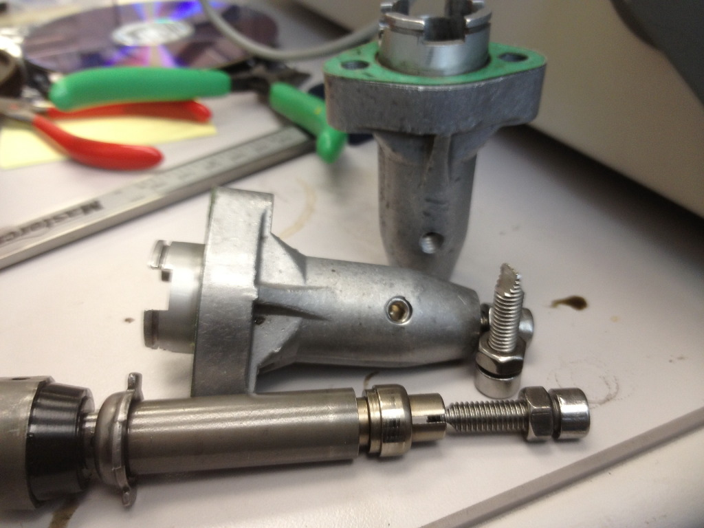
Above are the pics.. you can see how the set screw are installed and how the #6 screw driver tip bolt is installed.
Intstall on bike (I have not done this yet, but this is the plan)
Set timing.. install tensioner, and hold with screw driver, roll motor 2 or 3 rotations to make sure all the slack is out of chain..
Tighten the tensioner against the chain.. TITE!! using a screw driver through the top #6 hole.(don't flame me it will be loosened in a minut .
.
Note: I use loctite on everything!! CCT shaft screw, top screw and set screw!
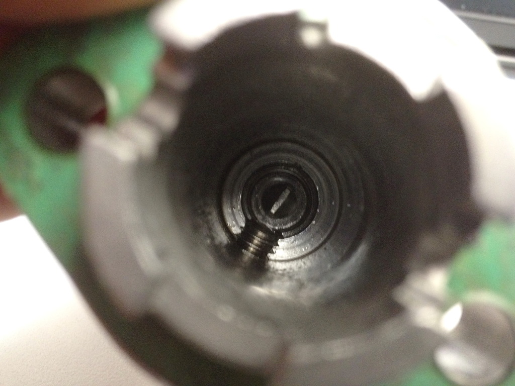
Install the top screw, as the screw tightens it will fall into the slot and begin to loosen the tensioner Tip looking through the set screw hole you can see the tentioner turn.. look for the slot give it a small turn (~1/8 should do it) and tighten the top nut against the tensioner to lock it in place. You want a little slack at in the end on the chain tentioner so check that the chain is not being held under heavy tension but can not come loose either.. , Note: on manual tensioner (ie. APE) they say tighten by hand and then turn 1/4 turn back out) this is the kind of slack I am referring to.. 1/4 turn on 1/4-20 bolt is NOT a 1/4 turn on the original CCT as it has about 13 threads per inch (measured) not 20.
Install set screw and tighten until firm.. it's only aluminium and not very thick so easy does it here!
That should do it
One last note on manual tentioners, they do have to be check and retightend from time to time.. my thought is about every 20,000 km, but feel free to chime in here. I'm thinking if a car is every year then that's about right.
This didn't have the effect your looking for. when the top M6 (screw driver) turns in the Original CCT is reverse thread and turns out! you can play until you get a setting your a happy with and lock it in.. but you can not adjust anything On the bike! this si the major shortcoming of the design.. I'm redo.. I don't recommend this setting after I installed it.
CCT failed.. bent all 4 valves.. have new head ready to go.. but need CCT's..
Read some things here about how to mod.. and this is what I did.
I liked the idea of the set screw in the side of the original CCT. However after drilling and tapping I wasn't as sure.. I had a friend (mechanical eng.) look at it and he said it was fine and would work.. but I'm Paranoid. I wanted something that would compliment the Set screw as the holes were already there.
This is what I came up with.. Put two ideas from the forum together.
here we go..
Parts #6 metric bolt 25mm long.. stainless preferred. Grind mill or file the tip until you have a slot screwdriver type tip that fits in the CCT (mine is 1mm wide done on a milling machine) Pick a suitable set screw for the side, I choose 1/4-20 by 1/4 long. I regret this as 20 is a little course.. a 32 or 36 thread count may have been a better choice and you don't need to be as big as 1/4.. so your call here.
Disassemble CCT.. all of it! including the top bolt
Measure .717" from the top of the CCT, mark, center tap and drill with a drill press. then tap (1/4-20 requires a #7 drill bit)
Above are the pics.. you can see how the set screw are installed and how the #6 screw driver tip bolt is installed.
Intstall on bike (I have not done this yet, but this is the plan)
Set timing.. install tensioner, and hold with screw driver, roll motor 2 or 3 rotations to make sure all the slack is out of chain..
Tighten the tensioner against the chain.. TITE!! using a screw driver through the top #6 hole.(don't flame me it will be loosened in a minut
Note: I use loctite on everything!! CCT shaft screw, top screw and set screw!
Install the top screw, as the screw tightens it will fall into the slot and begin to loosen the tensioner Tip looking through the set screw hole you can see the tentioner turn.. look for the slot give it a small turn (~1/8 should do it) and tighten the top nut against the tensioner to lock it in place. You want a little slack at in the end on the chain tentioner so check that the chain is not being held under heavy tension but can not come loose either.. , Note: on manual tensioner (ie. APE) they say tighten by hand and then turn 1/4 turn back out) this is the kind of slack I am referring to.. 1/4 turn on 1/4-20 bolt is NOT a 1/4 turn on the original CCT as it has about 13 threads per inch (measured) not 20.
Install set screw and tighten until firm.. it's only aluminium and not very thick so easy does it here!
That should do it
One last note on manual tentioners, they do have to be check and retightend from time to time.. my thought is about every 20,000 km, but feel free to chime in here. I'm thinking if a car is every year then that's about right.
Last edited by Renderw; Sep 24, 2012 at 06:46 AM.

Out of my mind, back in 5
MotoGP
Joined: Nov 2006
Posts: 6,109
From: Skurup, Sweden
So you have made a manual CCT with several moving parts inside that can fail/move... Congratualations, now you have the worst of two worlds...
Very ingenious to think it out, but I still think it's a bad idea... A simple carriage bolt cannot fail, if you tighten it correctly, and lock it...
Very ingenious to think it out, but I still think it's a bad idea... A simple carriage bolt cannot fail, if you tighten it correctly, and lock it...
Thread Starter
Member
Squid
Joined: Aug 2012
Posts: 68
So you have made a manual CCT with several moving parts inside that can fail/move... Congratualations, now you have the worst of two worlds...
Very ingenious to think it out, but I still think it's a bad idea... A simple carriage bolt cannot fail, if you tighten it correctly, and lock it...
Very ingenious to think it out, but I still think it's a bad idea... A simple carriage bolt cannot fail, if you tighten it correctly, and lock it...
I see you posted a lot on this, obviously more experience then me. What do you use for your CCT?
Last edited by Renderw; Aug 16, 2012 at 01:07 PM.
Out of my mind, back in 5
MotoGP
Joined: Nov 2006
Posts: 6,109
From: Skurup, Sweden
I can't be bothered to link it, it's been posted about a dozen of times already... Do a search and it's easy to find...
Take the stock housing, put it in a drillclamp, and enlarge the hole, make new threads and stick a carriage bolt in there... Add a nut, locked by an nyloc nut, and top the end of the threads with an acorn nut for a hold when adjusting... One single piece of metal all the way through with plenty of thread makes the only semi moving part, and two nuts tightened together will not move regardless of the vibrations...
I have used it for 4-5 years now, and checked it a total of two times since installation, both times completely unneccesary...
Thread Starter
Member
Squid
Joined: Aug 2012
Posts: 68
I assume this is the link you are refering to?
https://www.superhawkforum.com/forum...-manual-27539/
https://www.superhawkforum.com/forum...-manual-27539/

Senior Member
SuperSport
Joined: Nov 2011
Posts: 700
What you're forgetting is that the reason the cct fails is the spring inside breaks. For your design to work you still need that spring inside, so when that spring breaks you are **** out of luck. The original internals can not be used without the spring since the part that presses on the guide is a sleeve and is not able to apply tension without the spring.

Escape Reality
SuperSport
Joined: Jun 2006
Posts: 612
From: KANATA, KANADA
What you're forgetting is that the reason the cct fails is the spring inside breaks. For your design to work you still need that spring inside, so when that spring breaks you are **** out of luck. The original internals can not be used without the spring since the part that presses on the guide is a sleeve and is not able to apply tension without the spring.
I don't think this is inherently bad, it is just more complicated than necessary. Additionally, the set screw will actually be a bad thing here since it put pressure on the piston that is only held on one end if the bolt head is out of it's seat. If tighten too tightly, the piston will be pivoted to the side. If you allow the bolt head to rest on the seat in which it was designed for which then would allow the set screw to be effective then you must adjust the CCT to the right length first as you can't adjust it afterwards as it can only back out or in x amount since backing out too much will lose contact with the flat screw and too much in then the bolt is out of the seat.
I prefer the simpler way with the bolt through the middle as tweety referred to and what APE and others have done. That said I also did my CCT in a similarly fashion as ren. My version require that the piston and the bolt be permamently affix to one another with the piston bolt screwed all the way tight. The CCT then is adjusted using a longer bolt. This way, it is fully adjustable yet retained OEM look and contact point with the chain guide.
Thread Starter
Member
Squid
Joined: Aug 2012
Posts: 68
I think you guys missed a few things here. and it may be my first picture that casued this. The shoulder that bolts the top of the oem shaft = "piston" is much deeper then my picture shows, so providing the top of the "pison" is pushing tight against the top of the sleve (M6 out of the way at this point) then the set screw locks it very well. the idea was to move the M6 down until it too engaged the Piston but did not "PUSH" on it, simply fits in the slot and can be locked out..
As for positioning with the M6 bolt out.. use a screw driver set it tight (no springs anywhere -"AKA") and then move the screw driver and tighten the bolt..
Will it work? I'll let you know!
As for positioning with the M6 bolt out.. use a screw driver set it tight (no springs anywhere -"AKA") and then move the screw driver and tighten the bolt..
Will it work? I'll let you know!
Last edited by Renderw; Aug 16, 2012 at 07:07 PM.

Senior Member
SuperSport
Joined: Jul 2012
Posts: 582
From: Santa Fe, New Mexico
this may be a dumb question but here goes: why not insert another spring in there? Use a stronger spring that can be adjusted with the screw/bolt. If the tension could be adjusted on a spring it would manage constant pressure and would move according to slack in the timing chain more like the OEM part. (I am convinced that the manual CCT is best for me, this is just an idea that crossed my mind as I was reading the thread).
Senior Member
SuperSport
Joined: Nov 2011
Posts: 700
My mistake, I didn't read it all the first time and just now noticed the lock nut. I thought you would be using an otherwise stock unit just with an adjustment screw.
It should work, its just more intricate and has more parts that can fail than a carriage bolt.
It should work, its just more intricate and has more parts that can fail than a carriage bolt.
Out of my mind, back in 5
MotoGP
Joined: Nov 2006
Posts: 6,109
From: Skurup, Sweden
this may be a dumb question but here goes: why not insert another spring in there? Use a stronger spring that can be adjusted with the screw/bolt. If the tension could be adjusted on a spring it would manage constant pressure and would move according to slack in the timing chain more like the OEM part. (I am convinced that the manual CCT is best for me, this is just an idea that crossed my mind as I was reading the thread).
It's just that any spring what-so-ever will eventually fail if you subject it it a million small cycles, as it's subjected with here... And the seat for the locking parts also wear if they are oil starved, which is likely for them to become... So, as a result, no matter what spring, as soon as something can move, it will wear... Spring or seat, it's equally bad... It will fail...
So in the above idea, with no spring, yes it's better than what I thought, but I still think it's over complicated... And I still think it makes the adjustment more finicky than a straight carriage bolt, and it seems people have a hard enough time getting that right, so why add complication?

Just hangin' out
Back Marker
Joined: Apr 2011
Posts: 136
From: Delaware, Ohio USA
this may be a dumb question but here goes: why not insert another spring in there? Use a stronger spring that can be adjusted with the screw/bolt. If the tension could be adjusted on a spring it would manage constant pressure and would move according to slack in the timing chain more like the OEM part. (I am convinced that the manual CCT is best for me, this is just an idea that crossed my mind as I was reading the thread).
The various instructions for adjustment of manual tensioners all focus on one goal - zero actual tension on the cam drive chain and as near to zero play in the cam drive.
How do I know this? Well, the Yamaha SR500 (among others over the years) has a manual tensioner set up. They go as far as to put an indicator system on it to show proper adjustment. They have a sort of pin set up that goes down through the center of the adjuster bolt. When there is play in the drive that pin tip (head is against the slider) will be visibly bouncing in and out slightly (or a lot if not adjusted for a long time) at the end of the adjuster bolt. The adjuster bolt is turned very slowly in until the movement stop - the point at which there is no play in the cam drive - no further in, which would put tension on the chain. Then the adjuster nut is locked down with the large exernal nut/cover. Zero tension and near zero play in cam drive.
To the OP:
The only thing I see that is unnecessary in this whole plan is the set screw. If you tighten the locking nut properly there is no need for the set screw. All it does is screw up the threads on the adjuster, making it harder to do future adjustments.
The whole thing is more complex than needed. The simple thru bolt with locking nut set up is simple and extremely efficient. Two moving parts - the adjuster bolt and the locking nut - it just doesn't get any simpler. I sell them because not everyone wants to take time, has skills, has equipment, or has the knowledge to make the manual tensioner. Some riders, like I was before I started making the tensioners, simply want to buy a part, bolt it in and set it up. They don't want to have to bother with all the rest of the work to make the actual part - threading holes straight isn't always easy. I ended up making them because I made extra when I made the one for my bike - it snowballed from there.
If it was me doing what you're doing, I'd do what I originally did on my KLX and what the tensioners most of us make and sell did - make it a simple thru bolt for the adjuster and put a locking nut on it. The simpler it is the better it is. Before I did mine I talked it over at length with a few trusted friends/motorcycle mechanic/techs with quite a resume of skills and knowledge. When I started actually making them from scratch I decided what I wanted in one: I added flush mount fasteners and added an oil seal on the adjuster bolts to make it look cleaner and neater.
But do it how you want, just don't include any spring to push on the plunger, they have no positive function in a manual adjuster (the proper name for them, but everyone knows them as "tensioners"). There is supposed to be no tension on the chain.
Last edited by klx678; Aug 19, 2012 at 11:26 AM.
Thread Starter
Member
Squid
Joined: Aug 2012
Posts: 68
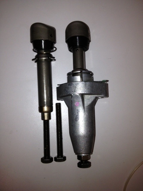
Ver 2.0 this seems to work much better!
not easy to drill.. what ever material this is HSS drill bits were having issues.. I used a leather and used a 4 flute HSS 1/4" bit. I ran that until it bottomed leaving a smooth bottom 1/4" round and ~1/4 deep. I then used a starting bit to center the hole and then a 15/64 bit to drill down 1/4". This allows the screw to go in the hole almost 1/2" I felt less then that and it may slip out, probably paranoid more then I should be.. but if your already drilling it doesn’t take much to go deeper..
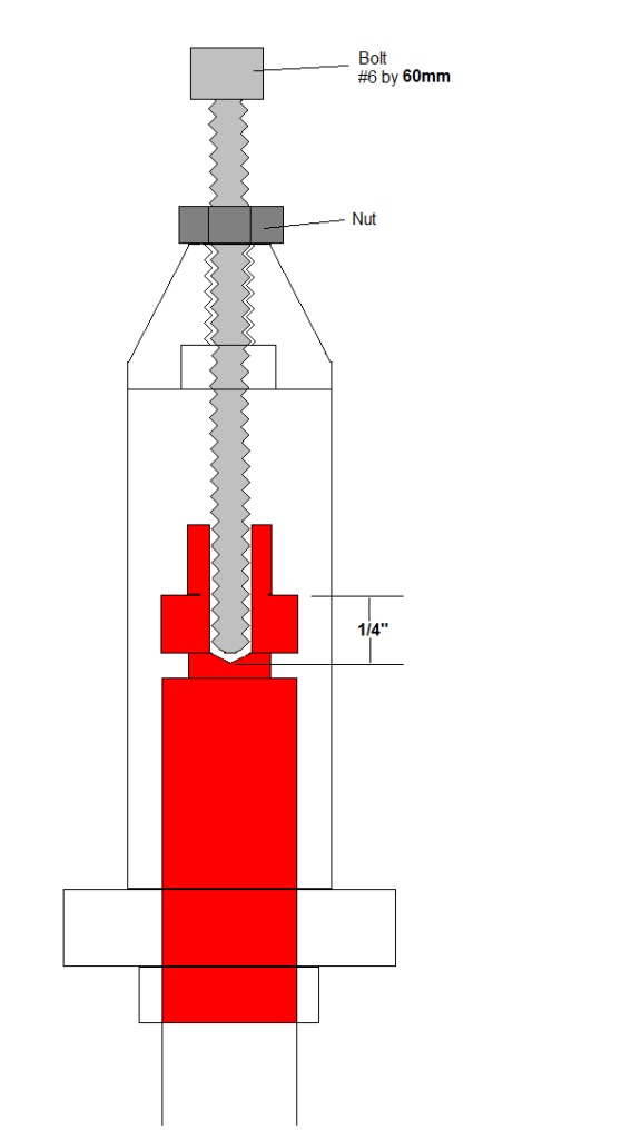
I think this pictures shows it best. below you can see how the screw inserts.. how deep it inserts and what it looks like when it's all done. Note this pictures shows a 50mm long M6.. in the end I choose to use a 60mm stainless M6.
Quick little video of them fitted to my bike and adjusting them.. it's not great.. buy maybe informative..
not easy to drill.. what ever material this is HSS drill bits were having issues.. I used a leather and used a 4 flute HSS 1/4" bit. I ran that until it bottomed leaving a smooth bottom 1/4" round and ~1/4 deep. I then used a starting bit to center the hole and then a 15/64 bit to drill down 1/4". This allows the screw to go in the hole almost 1/2" I felt less then that and it may slip out, probably paranoid more then I should be.. but if your already drilling it doesn’t take much to go deeper..
I think this pictures shows it best. below you can see how the screw inserts.. how deep it inserts and what it looks like when it's all done. Note this pictures shows a 50mm long M6.. in the end I choose to use a 60mm stainless M6.
Quick little video of them fitted to my bike and adjusting them.. it's not great.. buy maybe informative..
Last edited by Renderw; Sep 25, 2012 at 12:23 PM.

Thread
Thread Starter
Forum
Replies
Last Post
Crashrat
Classifieds
40
Oct 11, 2012 08:25 PM


