
Useful Strip down photos for a VTR Firestorm


Thread Starter
Junior Member
Squid
Joined: Aug 2011
Posts: 25

Useful Strip down photos for a VTR Firestorm
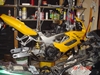
Decided to strip the bike to check the valve clearances on the rear cylinder, main reason was to cure a slight oil leak on the APE CCT. Here are some photos of the job. Note this is a 2002 F2 model with the 19l tank. You will see there is no tap so I had to be a little adaptive.
Disconnecting fuel sender unit
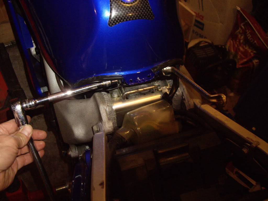
Loosening pivot bolt at the rear of the tank
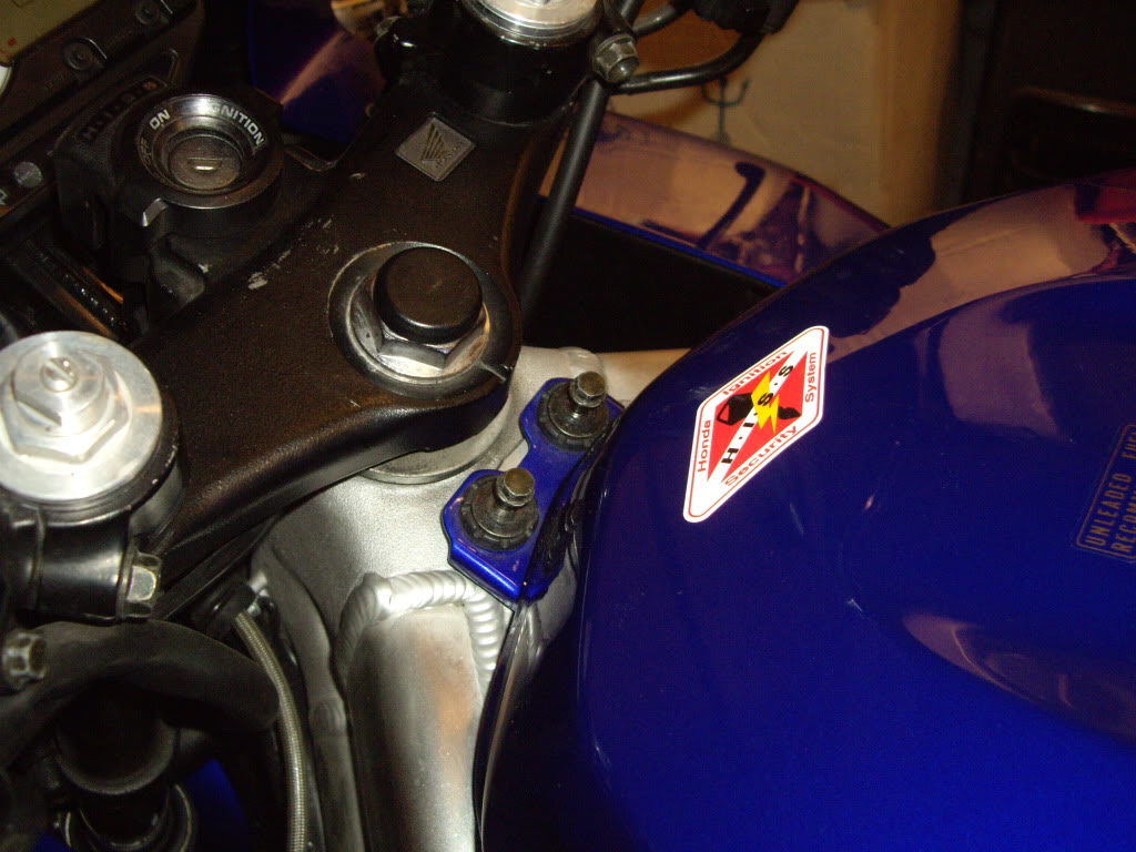
Removing front bolts
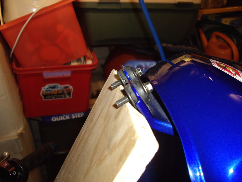
Support the tank using a piece of ply, note I use the tank bolts as added slippage protection
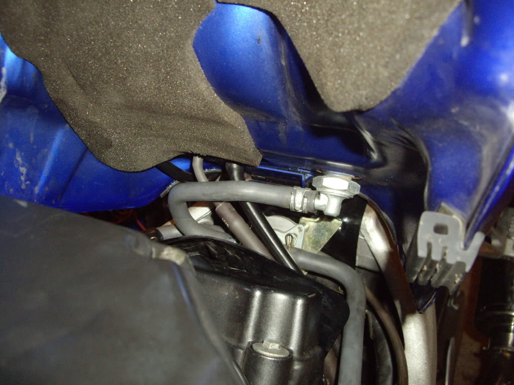
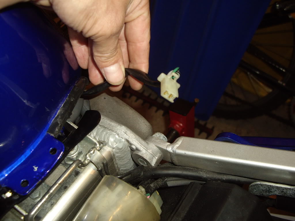
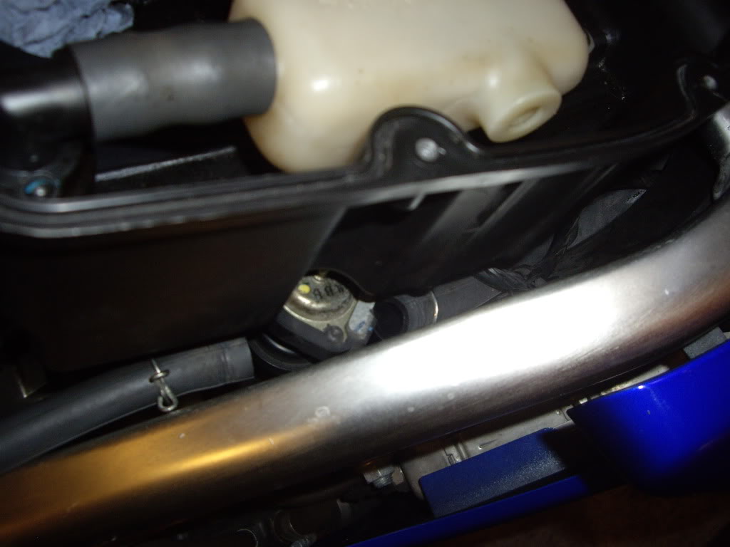
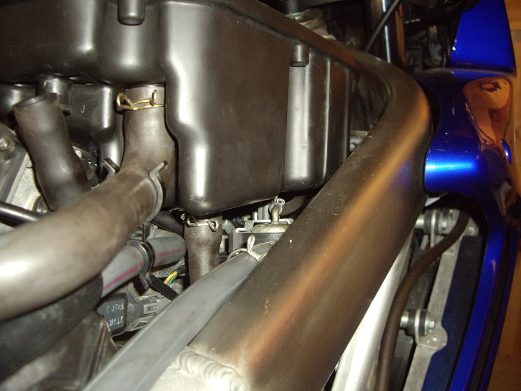
View under the tank note 2002 model and no shutoff valve.
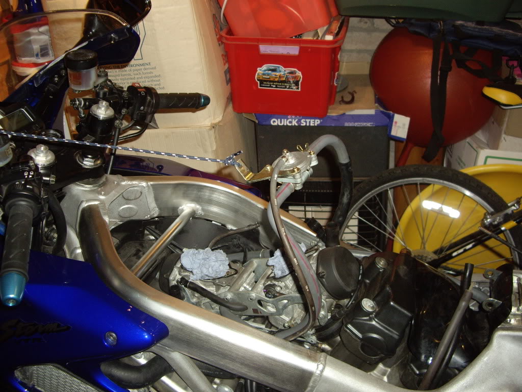
Adapted tool to clamp off the fuel line. Note, have as little fuel as possible in the tank. I had 1 bar on the fuel gauge
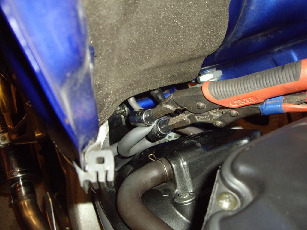
Fuel line clamped off. Note the square rubber tank protector (one on each side) in the foreground of the above photo can fall off, don't loose them.
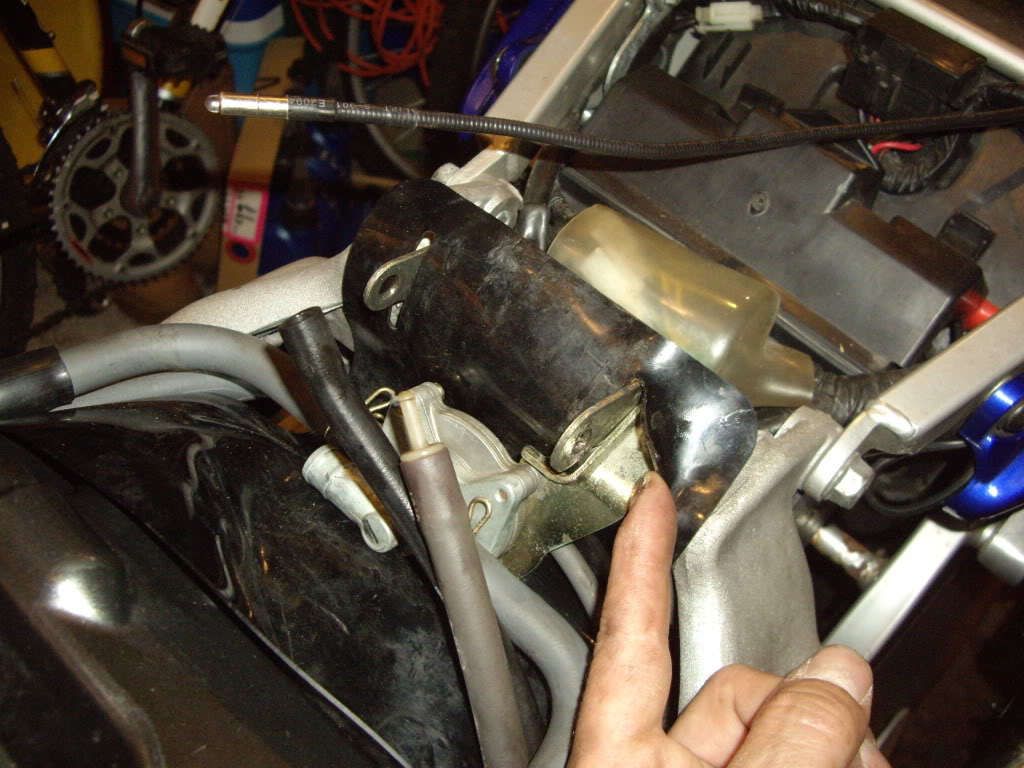
Next follow the main fuel delivery line from the left of the clamping device round to the fuel vacum assembly. Unscrew the fuel line clamp & pull off the fuel hose, there will be a little fuel spillage so have a rag at the ready. Then pull off the vacum & overflow pipes from the bottom of the tank. Those are the 2 pipes still attached to the tank avove the clamping device in the above photo. Note, I have alread removed the nut at the end of the pivot bolt ready for tank removal. Support the tank, remove the pivot bolt , and lift away. Place the tank somewhere safe & I plugged the fuel delivery pipe using a 12mm bolt wrapped with some PTFE tape, this allowed me to remove the clamping device so as not to damage the pipe any further.
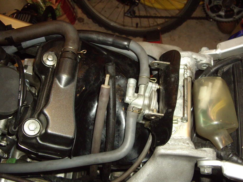
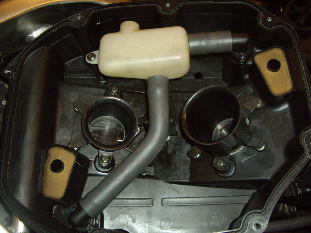
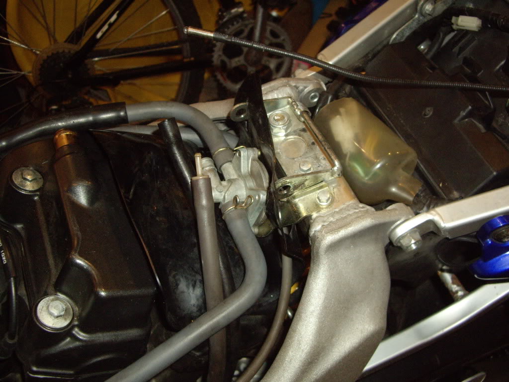
Photo of the tank removed showing the vacum assembly including both main carb fuel feed pipes and the small vacum control pipe.
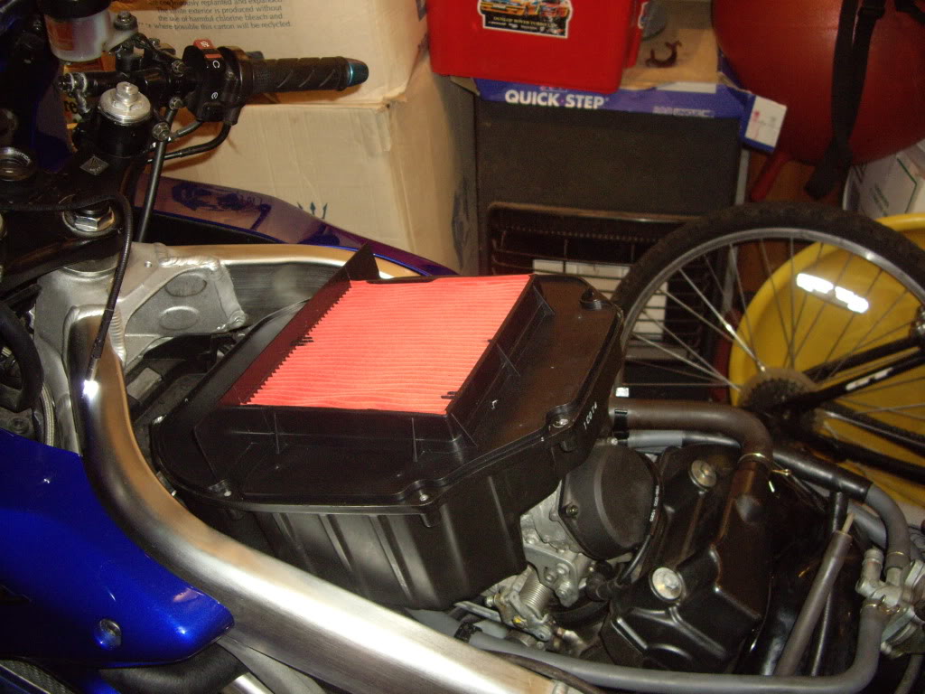
Airbox lid removed showing air filter. Note you can remove this lid & change the air filter without removing the fuel tank by having it pivoted virtically as shown earlier, please have an assistant available to support the tank as you remove the airbox lid just in case.
Air filter removed showing trumpets. Note: long trumpet at the rear & small at the front they are arrowed to the airbox housing as to correct orientation.
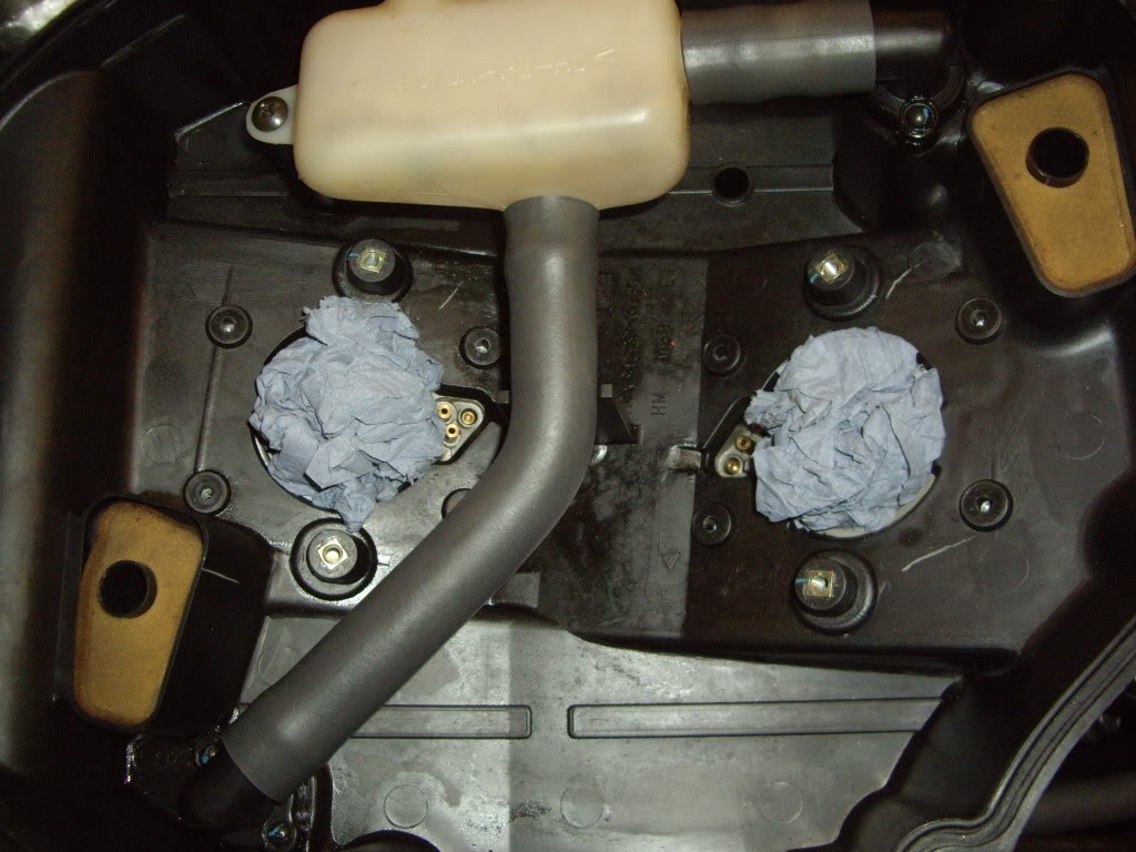
Trumpets removed & carb mouths secured against foreign bodies falling in.
Airbox housing is secured with 8 bolts which are thread locked in. These have now been removed. Now comes the plumping bit. The following are photos of various pipes that need to be removed that can be done in any order. Accessability & small hands are an advantage here.

Finally
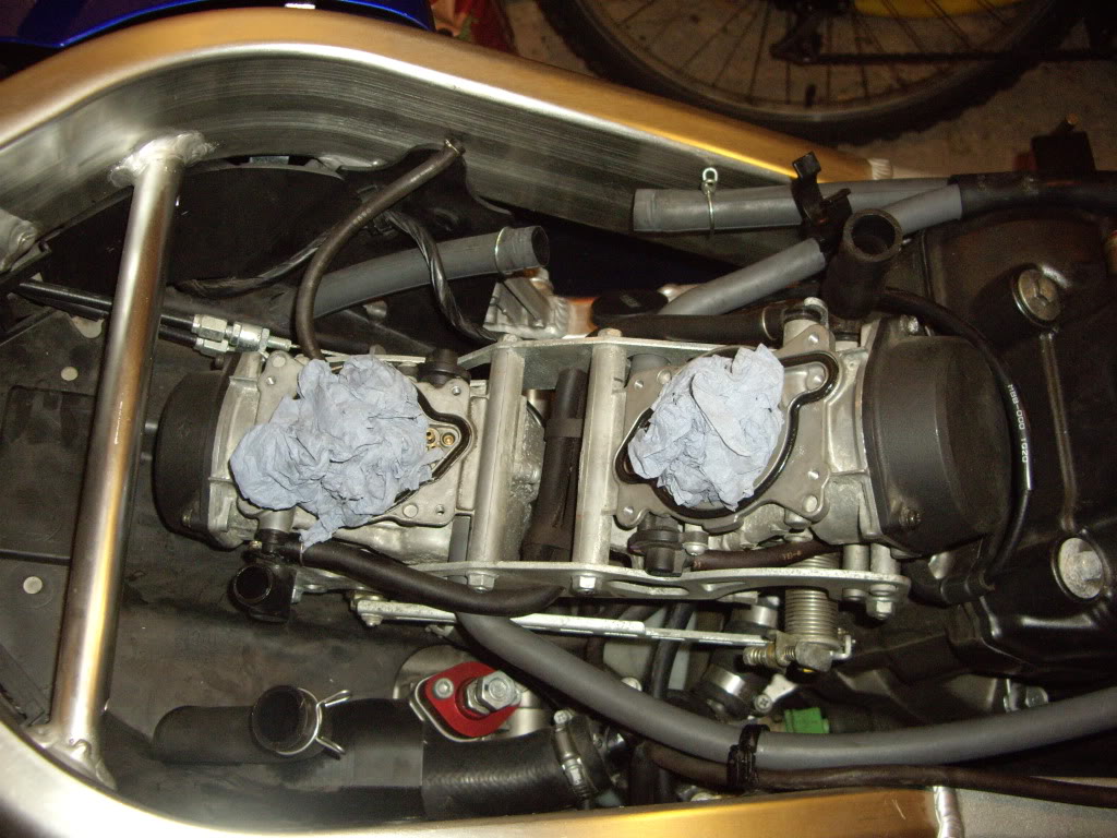
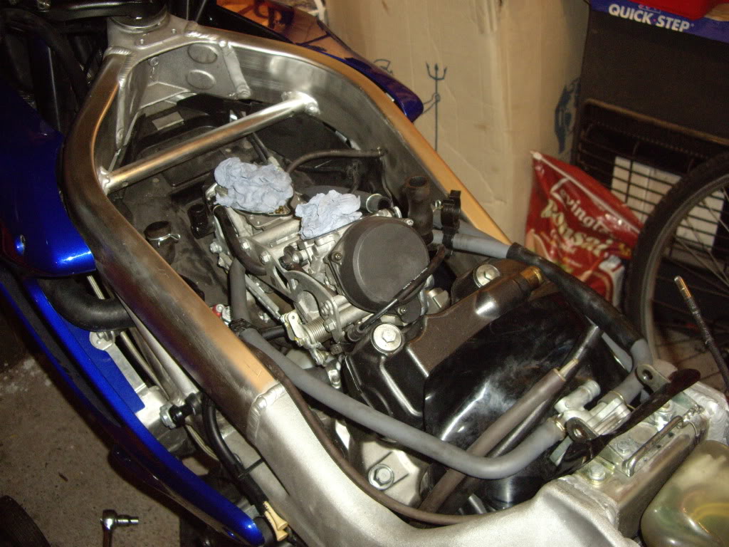
Airbox off. Next up is to remove the fuel vacum assembly
No need to remove all the fuel lines I supported it with a shoe lace attached to the wing mirror
The next sequence of photos is an aid to ensure you remove parts in a particular order so as to repeat in the re-assembly process
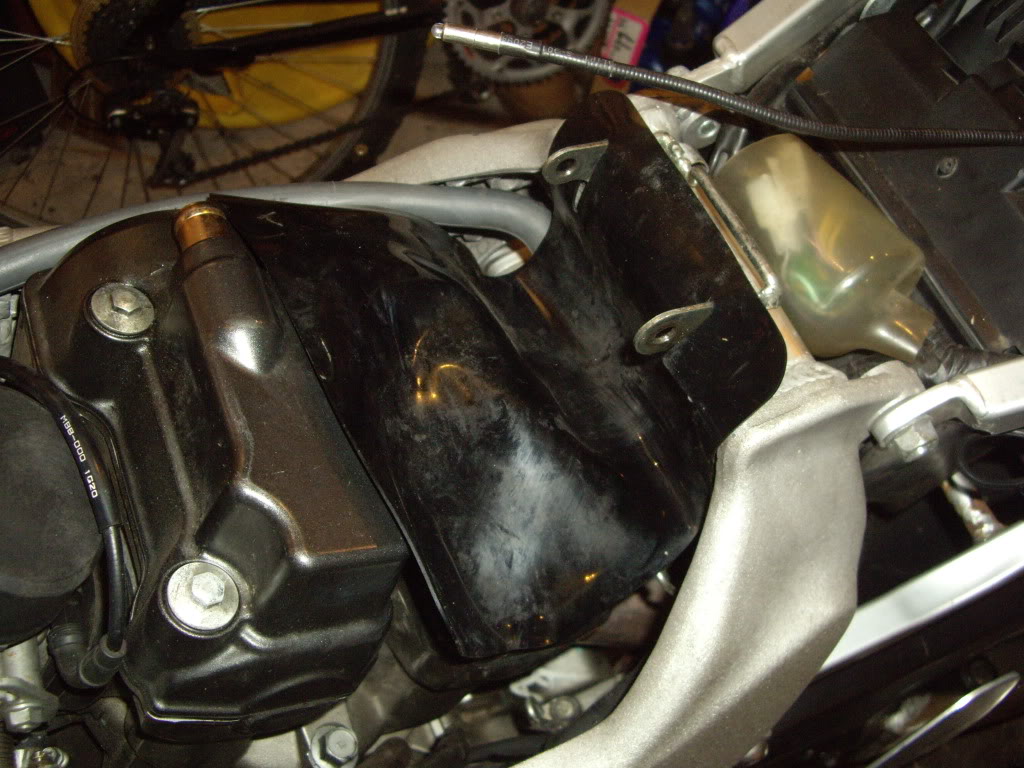
Remove rubber protector
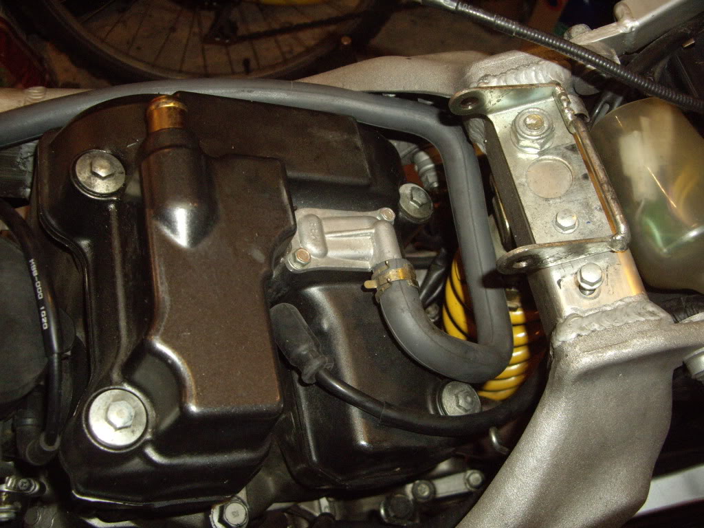
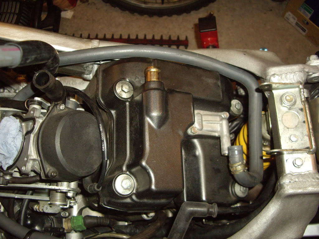
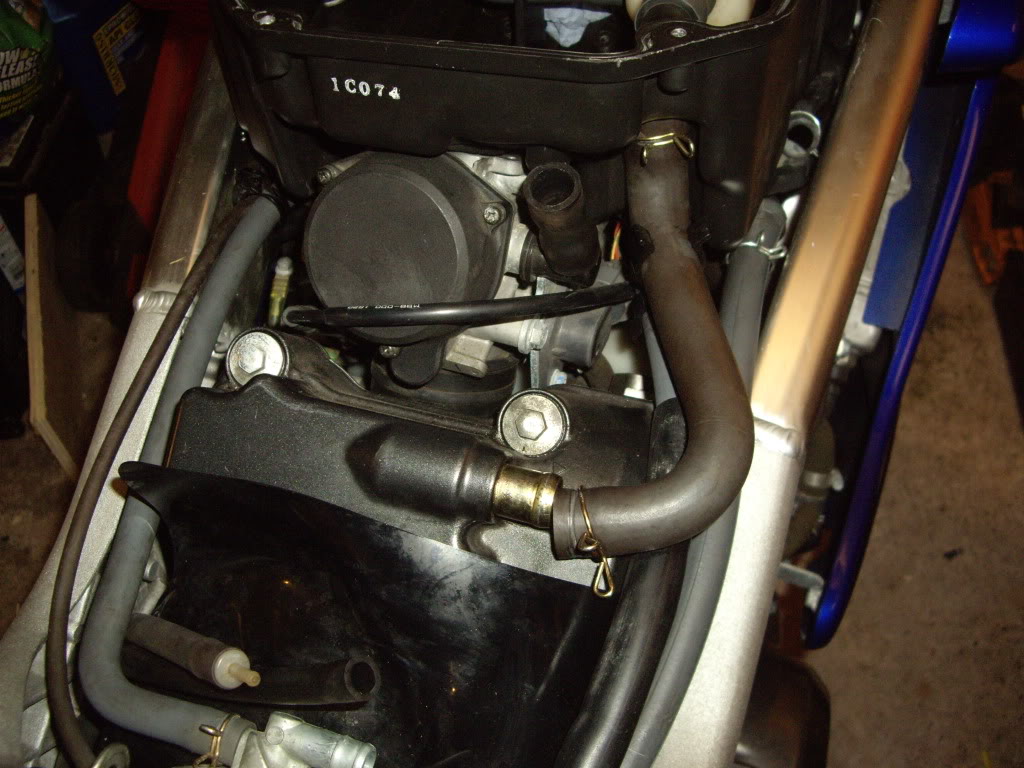
Disconnect & remove rear cylinder pair valve pipe.
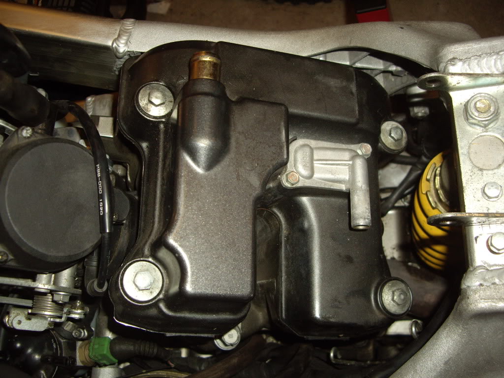
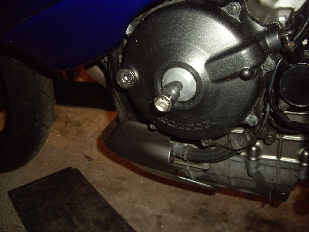
Now you have reached the rear cylinder rocker cover. Before removing first remove the altenator center plug. (AS STATED IN OTHER THREADS THIS IS MADE FROM A VERY SOFT ALLU & CAN BE A SOD :Argue 1: ) I tapped mine back & forth & it eventually gave way. You may want a spare ready just in case you need to bastardise it off. When replacing it use some grease on the threads this will help removal next time round. Then remove the timing access plug to the left of the center plug. NOW REMOVE THE SPARK PLUGS FOR BOTH CYLINDERS & COVER EXPOSED HOLES.
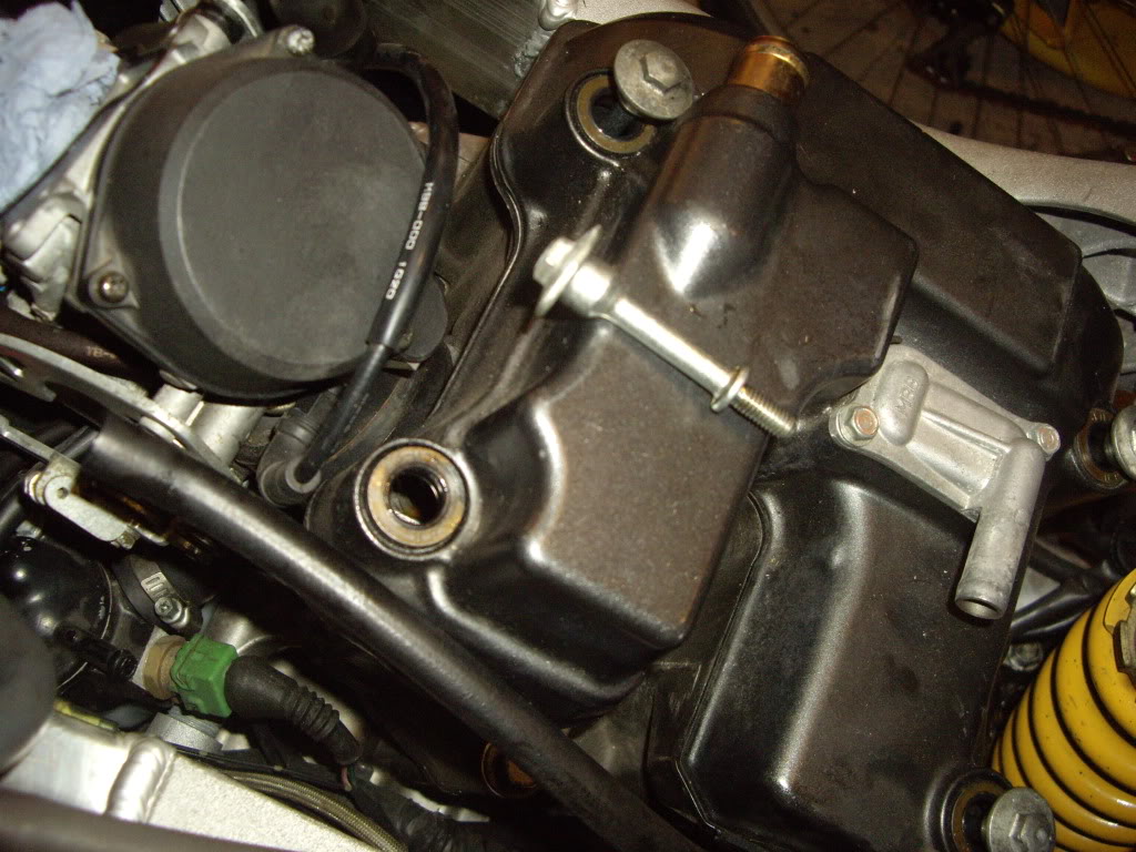
Next remove the 4 rockercover retaining bolts
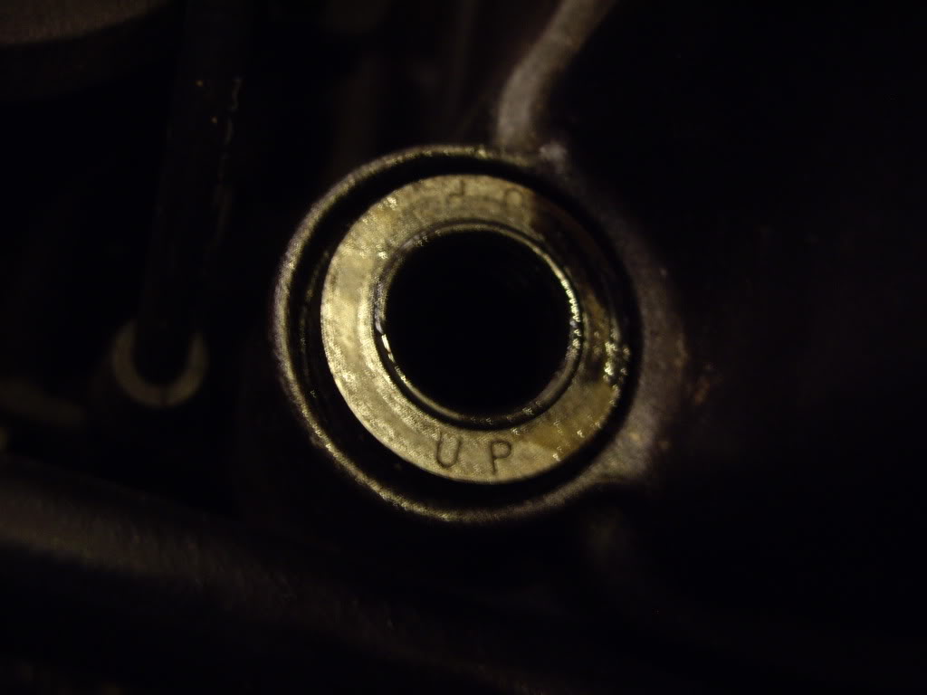
Note: the orientation of the washers the way UP is clearly stated on them. I also smear them with engine oil when replaced.
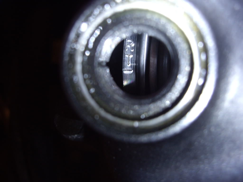
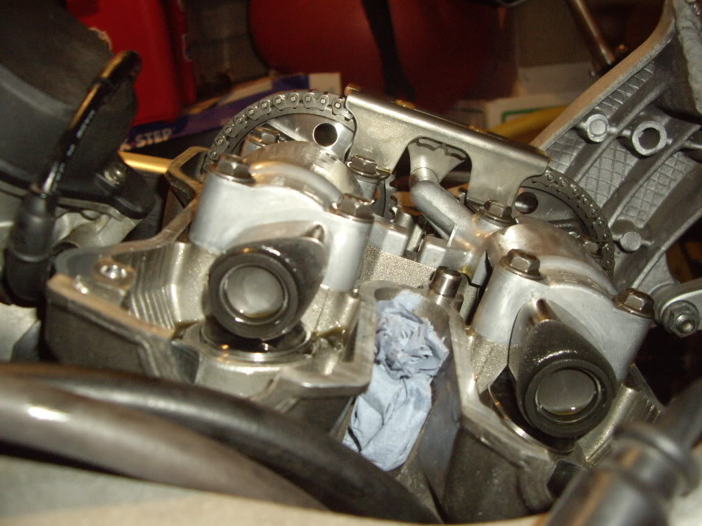
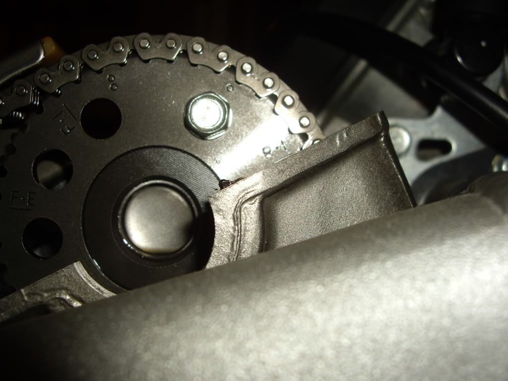
Next you need to find TDC for the REAR cylinder please refer to the CCT thread for this proceedure. Below are photos of what TDC looks like for the REAR cylinder looking at the cam lobes/sprockets & timing window. Note (ALWAYS TURN THE MOTOR COUNTER CLOCKWISE USING A 17MM SOCKET ON THE BOLT IN THE CENTER OF THE ALTENATOR HOUSING).
Reassembly is the reverse of what you have seen. This is as far as I went. My valve clearences are a shade on the tight side but have been reliably informed that they can wait for the the next workshop. I also stopped the leak on my APE CCT.
I hope this will help some of you out there I do like photos as they speak a thousand words. Happy spanners :thumbup:
Note I had to remove 7 photos from this post due to the 30 limit i believe the essence has not been lost.
Disconnecting fuel sender unit
Loosening pivot bolt at the rear of the tank
Removing front bolts
Support the tank using a piece of ply, note I use the tank bolts as added slippage protection
View under the tank note 2002 model and no shutoff valve.
Adapted tool to clamp off the fuel line. Note, have as little fuel as possible in the tank. I had 1 bar on the fuel gauge
Fuel line clamped off. Note the square rubber tank protector (one on each side) in the foreground of the above photo can fall off, don't loose them.
Next follow the main fuel delivery line from the left of the clamping device round to the fuel vacum assembly. Unscrew the fuel line clamp & pull off the fuel hose, there will be a little fuel spillage so have a rag at the ready. Then pull off the vacum & overflow pipes from the bottom of the tank. Those are the 2 pipes still attached to the tank avove the clamping device in the above photo. Note, I have alread removed the nut at the end of the pivot bolt ready for tank removal. Support the tank, remove the pivot bolt , and lift away. Place the tank somewhere safe & I plugged the fuel delivery pipe using a 12mm bolt wrapped with some PTFE tape, this allowed me to remove the clamping device so as not to damage the pipe any further.
Photo of the tank removed showing the vacum assembly including both main carb fuel feed pipes and the small vacum control pipe.
Airbox lid removed showing air filter. Note you can remove this lid & change the air filter without removing the fuel tank by having it pivoted virtically as shown earlier, please have an assistant available to support the tank as you remove the airbox lid just in case.
Air filter removed showing trumpets. Note: long trumpet at the rear & small at the front they are arrowed to the airbox housing as to correct orientation.
Trumpets removed & carb mouths secured against foreign bodies falling in.
Airbox housing is secured with 8 bolts which are thread locked in. These have now been removed. Now comes the plumping bit. The following are photos of various pipes that need to be removed that can be done in any order. Accessability & small hands are an advantage here.
Finally
Airbox off. Next up is to remove the fuel vacum assembly
No need to remove all the fuel lines I supported it with a shoe lace attached to the wing mirror
The next sequence of photos is an aid to ensure you remove parts in a particular order so as to repeat in the re-assembly process
Remove rubber protector
Disconnect & remove rear cylinder pair valve pipe.
Now you have reached the rear cylinder rocker cover. Before removing first remove the altenator center plug. (AS STATED IN OTHER THREADS THIS IS MADE FROM A VERY SOFT ALLU & CAN BE A SOD :Argue 1: ) I tapped mine back & forth & it eventually gave way. You may want a spare ready just in case you need to bastardise it off. When replacing it use some grease on the threads this will help removal next time round. Then remove the timing access plug to the left of the center plug. NOW REMOVE THE SPARK PLUGS FOR BOTH CYLINDERS & COVER EXPOSED HOLES.
Next remove the 4 rockercover retaining bolts
Note: the orientation of the washers the way UP is clearly stated on them. I also smear them with engine oil when replaced.
Next you need to find TDC for the REAR cylinder please refer to the CCT thread for this proceedure. Below are photos of what TDC looks like for the REAR cylinder looking at the cam lobes/sprockets & timing window. Note (ALWAYS TURN THE MOTOR COUNTER CLOCKWISE USING A 17MM SOCKET ON THE BOLT IN THE CENTER OF THE ALTENATOR HOUSING).
Reassembly is the reverse of what you have seen. This is as far as I went. My valve clearences are a shade on the tight side but have been reliably informed that they can wait for the the next workshop. I also stopped the leak on my APE CCT.
I hope this will help some of you out there I do like photos as they speak a thousand words. Happy spanners :thumbup:
Note I had to remove 7 photos from this post due to the 30 limit i believe the essence has not been lost.


Senior Member
SuperSport
Joined: Mar 2010
Posts: 987
From: Asheville, North Carolina
Well you have shown me some creativity (with the make-shift ,fuel clamps) and I am in agreeance with Smokin'Joe. I am just starting a from the frame build up(A real BASKET case- Superhawk) and you have shown me a reference to how to photo the process...
By the way- Not meaning to be nosey.. The propane heater in your photo- How well , or efficient are those heaters???
By the way- Not meaning to be nosey.. The propane heater in your photo- How well , or efficient are those heaters???

SportTouring
Superstock
Joined: Aug 2006
Posts: 274
From: Hawaii
I have a '98. I believe all the U.S. models were the same size(19l). On my tank the petcock is attatched to the tank with the on/off valve. Still great photos of what its like under the tank/ valve covers, for those who have not ventured that far yet.

Out of my mind, back in 5
MotoGP
Joined: Nov 2006
Posts: 6,109
From: Skurup, Sweden
It would be much easier to just unbolt the petcock from the frame, than clamping the tube... That's just making things more complicated than they have to be...
With the petcock unbolted, you just unhook the carb feed lines and vacuum lines and let it follow the tank... That's the same as you do on the older bikes where the petcock is attached to the tank...
Nice reference images though...
With the petcock unbolted, you just unhook the carb feed lines and vacuum lines and let it follow the tank... That's the same as you do on the older bikes where the petcock is attached to the tank...
Nice reference images though...
Out of my mind, back in 5
MotoGP
Joined: Nov 2006
Posts: 6,109
From: Skurup, Sweden
YOU ARE WRONG!!!!! Can't say it in a nicer way, sorry... And it keeps confusing the issue further when people do searches and find X amount of posts like yours with "beliefs"...
The US bikes all have a 16L tank, not one of them was ever delivered from the factory with a 19L tank... Not a single one... You can either trust me on that, or find out for your self...
In Europe and Canada, as well as the rest of the world, in 01 the tank was upgraded to a 19L tank, and the petcock was moved to the frame to make room for the extra volume... For whatever reason I dunno, but I guess to keep parts similar, Honda decided to make that same change in the US bikes, even if they kept the 16L tank...
Darkember is UK based, so he does indeed have the 19L tank...

Junior Member
Squid
Joined: Mar 2012
Posts: 27
From: Boston,ma
So today when adjusting my CCT on the front I believe it jumped 3 teeth based on the 3 clicks I heard...
Do both cams have identical markings to indicate where TDC is on each? I see your closeup of the right cam, but I don't see the left one.
Do both cams have identical markings to indicate where TDC is on each? I see your closeup of the right cam, but I don't see the left one.

Junior Member
Squid
Joined: Mar 2012
Posts: 27
From: Boston,ma
FI and FE, ignition and exhaust, gotcha, but what are they aligned with?
Basically how to I know if I am timed correctly or need to rotate one or the other based on the one that is always correct at TDC.
SportTouring
Superstock
Joined: Aug 2006
Posts: 274
From: Hawaii
O.K. Tweety, didn't mean to cause confusion. Didn't catch his location. Just wanted to repost the pictorial part of the undersides. I did realize that his was a '02. Though even if it was the a newer/ non-U.S model, it did help me before, in getting an idea of the various hook-ups and locations of parts. I thought that it might also help those searching and certainly did not mean to confuse anyone. I was not definetly sure so I did not want to say so. Comment well taken, will try to be more careful next time.
I certainly do not question your knowledge base.
I certainly do not question your knowledge base.
Out of my mind, back in 5
MotoGP
Joined: Nov 2006
Posts: 6,109
From: Skurup, Sweden
O.K. Tweety, didn't mean to cause confusion. Didn't catch his location. Just wanted to repost the pictorial part of the undersides. I did realize that his was a '02. Though even if it was the a newer/ non-U.S model, it did help me before, in getting an idea of the various hook-ups and locations of parts. I thought that it might also help those searching and certainly did not mean to confuse anyone. I was not definetly sure so I did not want to say so. Comment well taken, will try to be more careful next time.
I certainly do not question your knowledge base.
I certainly do not question your knowledge base.
Slacker
Superstock
Superstock
Joined: Jun 2005
Posts: 489
From: San Antonio, TX

SportTouring
Superstock
Joined: Aug 2006
Posts: 274
From: Hawaii
**Just a note to correct my previous post(#6) without losing the context of the thread.**
As pointed out by a very well knowledged member, the fuel tank size on my U.S. model
tank is 16L(4.23 gals), NOT 19L. Sorry for the confusion. (Thanks Tweedy).
(Maybe I was wishing too hard that I did have the larger non-U.S. tank. )
As pointed out by a very well knowledged member, the fuel tank size on my U.S. model
tank is 16L(4.23 gals), NOT 19L. Sorry for the confusion. (Thanks Tweedy).
(Maybe I was wishing too hard that I did have the larger non-U.S. tank

Seasoned tech
SuperSport
Joined: Apr 2012
Posts: 576
From: Issaquah, WA
Thanks tweety. I seem to recall seeing something saying that all the US models had the larger tank which I thought was 19L and then when he said he had the 19L tank with the different petcock I was a bit confused. What's the best way for someone in the US to acquire the 19L? Are there sites like Craigslist or other calssifides over there that a guy could look at?

Well take off, eh.
SuperBike
Joined: Jun 2012
Posts: 1,206
From: QC, Canada
Never saw this post, so took the time to read it.
Now, this is the fun part for me. I get to correct Tweety on misinformation about the tank size. No, Canada never got the 19L gas tank...;O)
Now, this is the fun part for me. I get to correct Tweety on misinformation about the tank size. No, Canada never got the 19L gas tank...;O)

Senior Member
SuperSport
Joined: Apr 2014
Posts: 932
From: Auckland, new Zealand

Thread
Thread Starter
Forum
Replies
Last Post
divingindaytona
Modifications - Cosmetic
1
Apr 6, 2006 10:29 PM


