
Turntech battery update


Senior Member
MotoGP
Joined: Jul 2010
Posts: 3,871
From: Phoenix, AZ

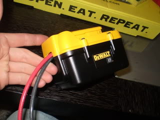
Yeah, they're connect at the bottom:
RWhisen! Gotta tell me these things before I buy and tear apart the battery pack! I picked 8 gauge cause that's what Tweety did. I used DeWalt cause it seemed to work for Lazn. I'm not wiring a balancer connection because as I understand it, these batteries won't be fully charged or fully discharged so it won't go out of balance...

Former Superchicken Owner
SuperBike
Joined: Sep 2008
Posts: 1,607
From: Ft. Worth, TX
I don't understand it at all...
RWhisen! Gotta tell me these things before I buy and tear apart the battery pack! I picked 8 gauge cause that's what Tweety did. I used DeWalt cause it seemed to work for Lazn. I'm not wiring a balancer connection because as I understand it, these batteries won't be fully charged or fully discharged so it won't go out of balance...
RWhisen! Gotta tell me these things before I buy and tear apart the battery pack! I picked 8 gauge cause that's what Tweety did. I used DeWalt cause it seemed to work for Lazn. I'm not wiring a balancer connection because as I understand it, these batteries won't be fully charged or fully discharged so it won't go out of balance...
Last edited by RWhisen; Dec 11, 2010 at 06:19 PM.
Senior Member
MotoGP
Joined: Jul 2010
Posts: 3,871
From: Phoenix, AZ
I will want to do this right eventually b/c of your suggestions, but for now think I'm gonna bow out of the balancer- I may look into your better batteries too. Urgh! I feel weird using a sub-par solution when there are better ones within my reach... but... gotta cut some projects short so that I can get this thing together!
Former Superchicken Owner
SuperBike
Joined: Sep 2008
Posts: 1,607
From: Ft. Worth, TX
Senior Member
MotoGP
Joined: Jul 2010
Posts: 3,871
From: Phoenix, AZ
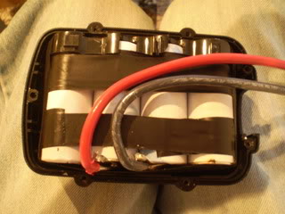
Ok wires are soldered on and I put the whole set back in the box. Not quite sure how I'm gonna connect it to the bike yet. Maybe a quick disconnect like earlier in this thread? I'm hoping to just attach this box somewhere as it has some mounting catches and then I'll have a DeWalt charged bike!
Seeing as my electrical system isn't hooked up yet, how do I test this thing? start my Shadow with it? or car? or use one of those volt meters? I think my roommate has one
Seeing as my electrical system isn't hooked up yet, how do I test this thing? start my Shadow with it? or car? or use one of those volt meters? I think my roommate has one

Senior Member
MotoGP
Joined: Jul 2007
Posts: 5,066
From: NYC
So tweety, I saw a guy on the SV forum selling similar units but he assured me it was only a good idea for racing. Said that in hot stop & go it would crap out running the fan constantly. Almost all my riding is like this so I didnt think these would work. Any input on that?
Senior Member
MotoGP
Joined: Jul 2007
Posts: 5,066
From: NYC
this is the link to the thread http://forum.svrider.com/showthread.php?t=135309

Administrator
MotoGP
Joined: Apr 2006
Posts: 4,402
From: Kempner, TX
So tweety, I saw a guy on the SV forum selling similar units but he assured me it was only a good idea for racing. Said that in hot stop & go it would crap out running the fan constantly. Almost all my riding is like this so I didn't think these would work. Any input on that?
2: The math says it works.
3: Some are building less then fully capable packs, thats fine, if they work on the cheap,,, more power to them,, but if they fail.. I think it disingenuous to use that example of why the A123 cell battery is not suitable.
4: It's just math.. have a look your self.. You need a decent multi meter with a clamp on inductive sensor for amperage. See what your amperage draw at the battery from wires that supply power to the system ....see what the draw is at rest, Key off,, key on, running at idle, running at idle with turn sig ,high beam and fan running and then do this all again at 4k RPM.
Same checks for voltage.
Now do the same amp checks with the charge wire from the R/R.
Same checks for voltage.
It's math... at any time did your battery supply more amperage then the R/R was putting in? At any time did the batter voltage drop below the key off resting battery voltage?
If you did not use more amperage from the battery then what the R/R is putting out your good.
If your battery voltage while running did not drop below battery resting voltage.. Your good.
Now for those that have not installed a new (better) R/R, upgraded the wiring for the charge circuit.. it may be an issue that I will never see on my bike.
Last edited by E.Marquez; Dec 12, 2010 at 06:34 AM.

Out of my mind, back in 5
MotoGP
Joined: Nov 2006
Posts: 6,109
From: Skurup, Sweden
I like larger gauge wires so you don't heat them up too much during use, 8 gauge would probably work fine. Any time you use batteries with cells like this they will not discharge or charge equally so a balancer is a requirement for me. I would guess that is why some of the guys who have had problems are having them, their cells need to be balanced or are not up to spec. I wouldn't imagine DeWalt uses the finest quality cells and I have had awesome experience with Hyperion cells in NiCad and LiPo types. Definately would not recommend either of those types for this application as the NiCad develops a serious memory problem and the LiPo is just too volatile (prone to fire) for this situation.
One, the DeWalt cells are manufactured by A123, and are the one and only propretiray cells manufactured directly by A123... And seeing as A123 is the company that developed and holds the main patents to the LiFePo4 chemistry cells, I highly doubt you will find better cells anywhere... The Hyperion 26650 cells are A123 cells with a new sleeve... Go pop the sleeve of and see for yourself... The other sized cells are not, but the
As for balancing, well that's a looong discussion... But let's just say this... with 8 cells in pairs of two making up a 12V battery, you do not need a balancing circuit as long as you follow a few simple rules...
As for your statment RWhisen, are you using a balancer on you lead batteries? No?! why not? they are cell based, ie they should according to your logic need a balancer! The reason they don't are tha same as to why the A123's don't folloing a few simple rules... The reason however that a SLA performs way worse than A123's is because of this, and the fact that their tolerances for this is way more lax... Measure the charge level on each cell in a SLA, and you will find that they get way out of balance when the charge drops, and hence are unable to supply usable voltage...
As for the A123's... Never, ever let a charger come near them (unless you know what you are doing and balancing them, with a circuit or with maths...
The reason is that as long as the cells stay in the mid 80% where they are neither full or empty, they are self balancing... And on a bike with a healthy charging system, they will be kept there during normal running... If you get them down to completely flat or insanely topped of, they are not...
And if you do that once, they balance out again by themselfes... If you run them flat, charge them and then run them flat again, they are imbalanced and you are risking to reverse a cell when they are nearing bottom the second time... Same goes for chargers... They top them off to a point where you get them out of balance and if you run them flat at that point you can damage them...
If you manage to run them dead flat, run the bike and pop the clutch and it's up and running (you will be half dead though) and charge the pack that way, or give it a half charge then take a ride...
As for wire size... The VTR takes 20-25A current at the most when starting... Running that though a #8 wire with good insulation means it will be warm to the touch, but it takes 45-50 minutes before you damage anything because of heat... And at that point the battery has been flat for 49 minutes... Running a larger wire means you incur a voltage drop based on increased wire resistance and capacitance... Basically #9 means .2V drop, #10 means .3V and so on... So #8 is about optimum... Anybody that wan'ts I'll provide the formula...
Also, the LiFePo4 cells needs to have some internal heat to perform at optimum, a larger wire means you will have a hard time starting in anything less than summer weather...
Last edited by Tweety; Dec 12, 2010 at 07:24 AM.
Out of my mind, back in 5
MotoGP
Joined: Nov 2006
Posts: 6,109
From: Skurup, Sweden
I'm splitting the post...
As for the SV thread... I'm to lazy to read it... But here is the answer to why it works...
Take the stock SLA battery... It's a 10Ah 12V nominal battery... A SLA battery is capable of providing it's nominal voltage between ~50% charge and full charge... It is capable of being discharged at 0.05C without sagging... Ie 10Ah means 1C is 10A... 0.05C means 0.5A... Anything higher than this and the battery voltage starts dropping like a stone...
Effectively this means that the SLA battery provides usable starting voltage ONLY when it's charged above 75%, and only during the first 45-60 seconds, then the voltage has sagged to low, and the battery needs 3x that time to rebound, ie let it sit for 3-4 minutes and you get another attempt... In terms of math, this means the 10Ah battery is a 2.5Ah starting battery, and in terms of slow discharge (<1A) it's a 5Ah battery...
The LiFePo4 cell provides starting voltage from ~5-8% charge to full charge, let's make the math easy and call it 10%...The max continous discharge is 70A, we are using 25A, which is way less... Not enough to make them sag measurably... Ie they are still a 4.2 Ah starting battery of the total 4.6Ah, compared to 2.5Ah of 10Ah... And as a slow discharge is even less taxing, here they still provide 4.2Ah vs the SLA's 5Ah...
And the above only applies when the SLA is brand spanking new and 100% charged, which it will rarely reach on a bike... The A123's will however hover at 95% charge after a mile or two and stay there so long as the bike is charging according to spec... At that point the 5Ah is probably around the 4.2Ah mark, so the difference becomes negligable...
Basic math say's the SV guy is talking complete bullshit... But who am I to argue if he doesn't want to sell his cells...
Out of my mind, back in 5
MotoGP
Joined: Nov 2006
Posts: 6,109
From: Skurup, Sweden
So tweety, I saw a guy on the SV forum selling similar units but he assured me it was only a good idea for racing. Said that in hot stop & go it would crap out running the fan constantly. Almost all my riding is like this so I didnt think these would work. Any input on that?
Administrator
MotoGP
Joined: Apr 2006
Posts: 4,402
From: Kempner, TX
As for wire size... The VTR takes 20-25A current at the most when starting... Running that though a #8 wire with good insulation means it will be warm to the touch, but it takes 45-50 minutes before you damage anything because of heat... And at that point the battery has been flat for 49 minutes... Running a larger wire means you incur a voltage drop based on increased wire resistance and capacitance... Basically #9 means .2V drop, #10 means .3V and so on... So #8 is about optimum... Anybody that wan'ts I'll provide the formula...
...
...

.. But the part reference voltage drop....... You way over simplified voltage drop based on wire size alone.. And I know you know that... so
Length of the conductor, material used in the conductor, method of attachment of each end of the conductor, type of conductor, solid....or??
Please.. include your formula for estimating voltage drop.., please be specific on the variables your basing the formula so others can measure and compare against a like set up..
Last edited by E.Marquez; Dec 12, 2010 at 07:37 AM.
Out of my mind, back in 5
MotoGP
Joined: Nov 2006
Posts: 6,109
From: Skurup, Sweden
Tweety, great post and concur with all.
.. But the part reference voltage drop....... You way over simplified voltage drop based on wire size alone.. And I know you know that... so
Length of the conductor, material used in the conductor, method of attachment of each end of the conductor, type of conductor, solid....or??
Please.. include your formula for estimating voltage drop.., please be specific on the variables your basing the formula so others can measure and compare against a like set up..
The parameters are pretty simple, total wire lenght is roughly 20 cm, since that is what is needed to cram it into the box, the wire I used is multistranded copper (standard hardness, not thin stranded) look for "battery cable" or "multistranded powercable" and you find an equivalent at most stores, the attachment is soldered one end and die-press crimped in the other (ie multiple press points), I calculated at 25C temp as that's roughly normal for my part of the world and used 13.5V as reference voltage since that is what a 12V nominal system is supposed to be...
But most of this becomes irrelevant as the parameters remains the same for a larger wire... The only thing that changes in this application is the wire... So for that, use any standard formula for voltage drop (google it)... And at that point you will find that my estimation was pretty fair for a 12V nominal system of this size... I think it came out to ~1% drop at 8# and 2,5% at 9# and so on... So ~0.1V for the #8, ~0.3V for #9, ie ~0.2V relative each other...
But yeah, I agree... To find the actual drop for the actual system, you need way more data... But if you use #8 cable marked as "battery cable" and less than a foot (more becomes a PITA) and solder and or crimp it with good tools, and compare it to #9 or #10 at the same parameters, the end result ends up around the numbers I mentioned...
Here are a whole bunch of usable formulaes... http://www.electrical-installation.org/wiki/Main_Page... Not the exact one's I used, but a good reference...
Remember... Teaching how to calculate stuff like this was my day job for a good while, give me a blackboard and I'll bore all of you to sleep...
Last edited by Tweety; Dec 12, 2010 at 08:17 AM.
Senior Member
MotoGP
Joined: Jul 2010
Posts: 3,871
From: Phoenix, AZ
Interesting stuff, guys.
E.m.-quick question to your earlier post. You mentioned upgraded charge wires on the R/R. What are these?
Tweety- actually the SV forum post confirms many of your statements including the brand A123 cells in the DeWalt pack. The guy selling the batteries only made a little fuss about whether to use 4 or 8 cell for the SV's as both will work, but 8 cell are a safer bet.
And if all I really need to do is clutch start this thing in an emergency to charge it... Hell, I'll do that every time to start the bike if I have to!
Out of my mind, back in 5
MotoGP
Joined: Nov 2006
Posts: 6,109
From: Skurup, Sweden
Interesting stuff, guys.
E.m.-quick question to your earlier post. You mentioned upgraded charge wires on the R/R. What are these?
Tweety- actually the SV forum post confirms many of your statements including the brand A123 cells in the DeWalt pack. The guy selling the batteries only made a little fuss about whether to use 4 or 8 cell for the SV's as both will work, but 8 cell are a safer bet.
And if all I really need to do is clutch start this thing in an emergency to charge it... Hell, I'll do that every time to start the bike if I have to!
E.m.-quick question to your earlier post. You mentioned upgraded charge wires on the R/R. What are these?
Tweety- actually the SV forum post confirms many of your statements including the brand A123 cells in the DeWalt pack. The guy selling the batteries only made a little fuss about whether to use 4 or 8 cell for the SV's as both will work, but 8 cell are a safer bet.
And if all I really need to do is clutch start this thing in an emergency to charge it... Hell, I'll do that every time to start the bike if I have to!
For race use, go as small and light as possible... For everyday, have a margin... For the VTR 8 cells are with margin...
As for upgraded R/R wiring... Use a R1 R/R and easternbeaver's harness and that is plenty (it has been mentioned and linked in several posts)... or do a DIY version...
Administrator
MotoGP
Joined: Apr 2006
Posts: 4,402
From: Kempner, TX

Senior Member
SuperBike
Joined: Aug 2005
Posts: 1,864
From: Fort Wayne, IN

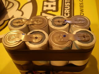
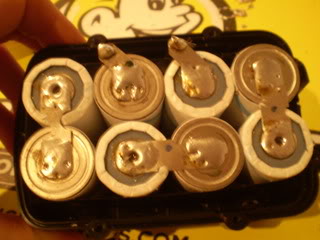
From what I can tell, you are keeping the cell configuration from the DeWalt pack. That's going to give you WAY too much voltage. You need to pull all of the cells out and separate them. Then solder it back up in a 2P-2P-2P-2P configuration. That nomenclature means that you have four sets of two cells, each set of two is in parallel and the four sets are in series. To do this, take two cells and solder the + sides together and the - sides together. Repeat three more times. Then take these sets and connect them +-+-+-+-. Each cell is ~3.3V, in parallel it doesn't change. Four in series gives you 13.2V nominal.
Here is a video of my bike being started with a 8-cell A123 about a year ago:
http://www.youtube.com/watch?v=uA7RRiw-1zo
Senior Member
MotoGP
Joined: Jul 2010
Posts: 3,871
From: Phoenix, AZ
Hahaha oh man you guys are gonna be the end of me! yeah, it's stock as it came out of the battery pack... I think this may address my confusion as to how a 28v pack works for a motorcycle that runs off of less than that. Back to the soldering iron, I guess. I'm guessing it's good that I didn't try to start anything with it yet!

Out of my mind, back in 5
MotoGP
Joined: Nov 2006
Posts: 6,109
From: Skurup, Sweden
Let's start with the basics... First, for reference #8 cable is roughly 8,5 mm2... And with a feet of cable being roughly 30 cm, two lengths of just under a feet side by side (each pole of the battery) means that for sake of easy math, say 50cm or 0.5m of wire...
The resistance in a conductor is RC = (Resistivity x Length)/Area
The resistivity of copper is 0,0175 Ohm mm2/m at 15�C and increases at 0.4% per degree over 15�C... Ie at 25�C it's 4% higher, (0,0175 x 1,04 = 0,0182)
A conductor of area A and length L will at 25�C have the resistance RC = 0,0182 x L/A
E.g. 50 cm of a 8,5mm2 copper conductor at 15�C has the resistance RC = 0,0182 x 0.5/8,5 = 0,0010705882352941 Ohm or ~0,001 Ohm
To calculate the voltage drop (UC) in the conductor you multiply the resistance with the current (I) in the conductor, i.e. UC = RC x I.
This means that with 25 A in the conductor in above example, the voltage drop will be UC = 0,001 x 25 = 0,0267 V in just the cable...
I didn't calculate the drop based on the solder and crimping, but rule of thumb is that you just measure the resistance of each junction and add that in the formula (slight simplification, but it works pretty good in real world applications...) In my case I got an added resistance of 0,004 Ohm's from the crimp and Anderson connector and no real measurable change from the soldering... End result of the resistance for the voltage drop is 0,001 + 0,004 = 0,005 Ohm and 0,003 x 25 = 0,125V as the voltage drop...
Again, even this is slightly simplified, but near enough for what we are calculating... And this is resistance alone... Ie it drops as the wire gets larger... (#7 is larger than #8, #9 is actually smaller)... Then comes the capacitance of the wire (which increases if the wire gets too large)... That's a whole new headache, and since it actually involves how far apart those wires are, and if and how near paralell they are, that ends up being a lot of guesswork and best cases...
Let's just say, that any time you can keep the voltage drop at as close to 1% for short wires an these voltages, ignore capacitance more or less and if it strays to far, ie close to 0 or to high, the calculations become annoying, the reason being that even while the resistance of a wire might measure as 0 Ohm or close to, for practical purposes, the rest of the world tends to interfere and mess that up...... But if you really wan't the science let me know, and I'll deal with that tomorrow... Need some sleep...
Last edited by Tweety; Dec 12, 2010 at 11:53 AM.

Senior Member
MotoGP
Joined: Mar 2007
Posts: 3,132
From: Phoenix, AZ
Hahaha oh man you guys are gonna be the end of me! yeah, it's stock as it came out of the battery pack... I think this may address my confusion as to how a 28v pack works for a motorcycle that runs off of less than that. Back to the soldering iron, I guess. I'm guessing it's good that I didn't try to start anything with it yet!
after you do that, flip one of the packs over to let you solder on to it and have two 14v (12v) batteries instead of 1 28v one.

Senior Member
MotoGP
Joined: Jul 2010
Posts: 3,871
From: Phoenix, AZ
Conflicting info here... so let's say "hypothetically" that I got excited and cut all of the batteries apart already  ... what I need to do is put them back the way they came, except for the one link connecting the two four packs, flip one of the packs, and have a positive and negative wire coming out from top and bottom?. I will probably wait just a little longer this time to get a few opinions! The way I was going, I would probably have thrown all of the batteries in a bucket of water if someone told me to...
Out of my mind, back in 5
MotoGP
Joined: Nov 2006
Posts: 6,109
From: Skurup, Sweden
Um... The easy way to make a pack is take the cells in pairs and solder them together positive poles and negative poles... That essentially gives you a "larger" cell with more capacity but the same voltage, ie still 3.3V... Then you take four of these pairs and line them up after each other, solder positive to negative poles making them into a 13.2V cell that has the positive pole and negative pole on opposite ends but same side of the pack... Then you solder wires to those... Easy...
Oh, and thinking first is over-rated... Highly practical, but over-rated...
Oh, and thinking first is over-rated... Highly practical, but over-rated...
Senior Member
MotoGP
Joined: Mar 2007
Posts: 3,132
From: Phoenix, AZ
Conflicting info here... so let's say "hypothetically" that I got excited and cut all of the batteries apart already ... what I need to do is put them back the way they came, except for the one link connecting the two four packs, flip one of the packs, and have a positive and negative wire coming out from top and bottom?. I will probably wait just a little longer this time to get a few opinions! The way I was going, I would probably have thrown all of the batteries in a bucket of water if someone told me to...
You need two separate packs of 4 cells each where it is just + to - soldered in a row. It was already configured at a chain of 8 cells, and by cutting it in half you would have already had the two packs of 4 cells.
The flipping a pack over just had to do with how Dewalt made it from the factory no longer applies since you can resolder them in any orientation.. (flipping one of the original packs over put the + and - leads of the two packs in a convenient position without the need to run wires all over the place)
Now that you can make it however you like just build them so that you end up with the + and - leads of the strings of 4 cells somewhere easy to attach to.

Senior Member
Superstock
Joined: Jul 2008
Posts: 320
Lazn's and Tweety's solutions sound to my stupid *** as two different ways to get to the same end result.
Either pair the cells in parallel, then chain those 4 pairs together in series (4 parallel pairs in series), or make two series of four, and connect those in parallel. Right?
Both give you 13.2V. Is one configuration "better" than the other?
Either pair the cells in parallel, then chain those 4 pairs together in series (4 parallel pairs in series), or make two series of four, and connect those in parallel. Right?
Both give you 13.2V. Is one configuration "better" than the other?
Out of my mind, back in 5
MotoGP
Joined: Nov 2006
Posts: 6,109
From: Skurup, Sweden
Correct, both give you the same 12.3V cell in the end... If you have the cells in clumps of the old DeWalt pack lazn's way is a lot easier... If you have loose cells, both are about as much work...
Having the cells in pairs give one distinct advantage though... The two cells in each pair act as one cell and are always in balance... But in a string of four cells you will always have differences, and with two stings there will also be adifference between the strings... So in terms of cell life, that option is a lot better...
Having the cells in pairs give one distinct advantage though... The two cells in each pair act as one cell and are always in balance... But in a string of four cells you will always have differences, and with two stings there will also be adifference between the strings... So in terms of cell life, that option is a lot better...
Senior Member
MotoGP
Joined: Jul 2010
Posts: 3,871
From: Phoenix, AZ
Ah- starting to get it now... Makes sense why Tweety's pics at the beginning of the thread look different too...
My personal situation may make it easiest to re-configure back to DeWalt's as I have all of the battery connectors still attached to the positive ends (I only cut them off of the negative) and any way that I tried to order them last night I would have had to make more cuts as well as get some battery connectors. So a balance of batteries will be less robust, but, hey, the biggest I can really screw this up is the $80 I'm out for a new battery pack!
And Lazn- I'm trying to keep the batteries cool as well. I ended up with an 80w soldering iron so it's only on there for 2 seconds and I wait for everything to cool down before making multiple solders.


