
Upgrading to a 01+ instrument cluster


Thread Starter
Senior Member
SuperSport
Joined: Dec 2008
Posts: 507
From: Arizona

Upgrading to a 01+ instrument cluster
I have always wished I had a clock & fuel level gauge, then after seeing Inderocker's 2005 instrument cluster in person I was sold. I have read a few threads on here with no confirmed completion(from what I could find) of this project, well I figured others must not be OCD like me so I decided to take on this project. I know it would be much easier to swap to another bikes cluster or even an aftermarket but I want to keep the stock appearance.
I ended up purchasing a set of 2005 gauges on Ebay and should be getting them in the next week.
I have read a few facts and rumors about the process that I still need to confirm:
Facts:
1. 98-00 have a split plug design for the cluster while the 01+ have a single plug
2. You must replace the fuel level sensor in the tank
Rumors:
1. You must replace thermostat switch (according to Ronayers.com 37760-MT2-003 is used from 98-2005)
2. You must replace the brain(from what I can see it was never changed during the years of the bike)
3. You must replace the speedometer sensor (according to Ronayers.com part number 37700-MBB-000 is used on 98-2005)
Goals I have in mind:
1. Not to cut the existing wiring harness but make a short adapter
2. Have the exact same miles on the odometer when I am done(Mine has 19000 and the new model has 17000.)I�m hoping I can get this certified somewhere so if I ever sell the bike.
What I need from you guys:
1. Help
2. Close up or macro shots of the 01+ plug that goes into the back of the cluster, each side of it if possible, any identification marks on the plug as well so I can find one on the market somewhere.
3. The front end of an 01+ wiring harness for some of the wires and more importantly the plug that goes into the cluster so that I can make my adapter
4. A pre 01 instrument cluster or at least the wires off the back including the plug that attaches to the wiring harness so that I can make my adapter
Taking a quick look at the wiring diagrams in the manual it looks pretty clear cut of what needs to happen, In fact it looks like Honda was nice as most if not all of the same wire colors were used to each gauge in the instrument cluster.
I may have missed a thread so if you have any confirmed information that would be helpful please chime in. This project may take a while but hopefully I can get it done in my lifetime J

Out of my mind, back in 5
MotoGP
Joined: Nov 2006
Posts: 6,109
From: Skurup, Sweden
Well... I can debunk some of those rumors right away... The speedo and "brain" as you put it is completely the same... The temp sensor though will need to be replaced if you want an accurate display... The calibration is of by a mile on the old and new so it's most likely going to tell you that you are overheating when idling from a cold start...
As for the adapter... Well it's a good idea, but unless you get a killer deal on a wiring harness it's not going to be cheap...
When I helped a friend do this swap I took the leads from his defunct old unit (find a broken/crashed one on ebay for $10) and soldered the leads to the display permanently, that way the plugs match the old harness and I could seal it up against moisture real good... If you have reasonable skill with a soldering iron it's not too complicated...
The odo can be corrected using an signal generator giving a 0-5V square wave (nearest physics lab or electronics workshop)... it simulates the speedo/odo signal and ticks on the miles... Not possible to reverse it though before anybody asks that dumb question... Or you can sit there with a button... 0V-5V-0V... might wear your finger out though...
As for the adapter... Well it's a good idea, but unless you get a killer deal on a wiring harness it's not going to be cheap...
When I helped a friend do this swap I took the leads from his defunct old unit (find a broken/crashed one on ebay for $10) and soldered the leads to the display permanently, that way the plugs match the old harness and I could seal it up against moisture real good... If you have reasonable skill with a soldering iron it's not too complicated...
The odo can be corrected using an signal generator giving a 0-5V square wave (nearest physics lab or electronics workshop)... it simulates the speedo/odo signal and ticks on the miles... Not possible to reverse it though before anybody asks that dumb question... Or you can sit there with a button...
Thread Starter
Senior Member
SuperSport
Joined: Dec 2008
Posts: 507
From: Arizona
Well... I can debunk some of those rumors right away... The speedo and "brain" as you put it is completely the same... The temp sensor though will need to be replaced if you want an accurate display... The calibration is of by a mile on the old and new so it's most likely going to tell you that you are overheating when idling from a cold start...
As for the adapter... Well it's a good idea, but unless you get a killer deal on a wiring harness it's not going to be cheap...
When I helped a friend do this swap I took the leads from his defunct old unit (find a broken/crashed one on ebay for $10) and soldered the leads to the display permanently, that way the plugs match the old harness and I could seal it up against moisture real good... If you have reasonable skill with a soldering iron it's not too complicated...
The odo can be corrected using an signal generator giving a 0-5V square wave (nearest physics lab or electronics workshop)... it simulates the speedo/odo signal and ticks on the miles... Not possible to reverse it though before anybody asks that dumb question... Or you can sit there with a button... 0V-5V-0V... might wear your finger out though...
As for the adapter... Well it's a good idea, but unless you get a killer deal on a wiring harness it's not going to be cheap...
When I helped a friend do this swap I took the leads from his defunct old unit (find a broken/crashed one on ebay for $10) and soldered the leads to the display permanently, that way the plugs match the old harness and I could seal it up against moisture real good... If you have reasonable skill with a soldering iron it's not too complicated...
The odo can be corrected using an signal generator giving a 0-5V square wave (nearest physics lab or electronics workshop)... it simulates the speedo/odo signal and ticks on the miles... Not possible to reverse it though before anybody asks that dumb question... Or you can sit there with a button...
Do you happen to have pics of the solder job you did on the speedo, thanks for the help.
Out of my mind, back in 5
MotoGP
Joined: Nov 2006
Posts: 6,109
From: Skurup, Sweden
Awesome help! I will start looking for the new temp sensor. I did not think about soldering an old dongle onto the new gauges, I may have to look into that. As far as my soldering skills go, I still have one eye left after the last incident. The odometer adjustment is good information, I was thinking of rigging up a button that would be hit by something attached to a drill to keep pressing it, I figured it wouldnt take that long.
Do you happen to have pics of the solder job you did on the speedo, thanks for the help.
Do you happen to have pics of the solder job you did on the speedo, thanks for the help.
Nope... not going to happen...

Senior Member
MotoGP
Joined: Mar 2007
Posts: 3,132
From: Phoenix, AZ
Awesome help! I will start looking for the new temp sensor. I did not think about soldering an old dongle onto the new gauges, I may have to look into that. As far as my soldering skills go, I still have one eye left after the last incident. The odometer adjustment is good information, I was thinking of rigging up a button that would be hit by something attached to a drill to keep pressing it, I figured it wouldnt take that long.
Do you happen to have pics of the solder job you did on the speedo, thanks for the help.
Do you happen to have pics of the solder job you did on the speedo, thanks for the help.
Thread Starter
Senior Member
SuperSport
Joined: Dec 2008
Posts: 507
From: Arizona
Just an update my friend Pete does have the signal generator that will do what we need it to, I have found a first gen speedo with the attached wiring should be here within a week. I think I may solder onto the new speedo...unless anyone has a wiring harness from a 01+ they can sell me. If anyone has the pics of the plug that would be great, maybe some numbers off it, I may be able to find the plug on the internet.

Out of my mind, back in 5
MotoGP
Joined: Nov 2006
Posts: 6,109
From: Skurup, Sweden
Just an update my friend Pete does have the signal generator that will do what we need it to, I have found a first gen speedo with the attached wiring should be here within a week. I think I may solder onto the new speedo...unless anyone has a wiring harness from a 01+ they can sell me. If anyone has the pics of the plug that would be great, maybe some numbers off it, I may be able to find the plug on the internet.
")
Best bet is to find a used wire harness from a salvager on eBay...
Thread Starter
Senior Member
SuperSport
Joined: Dec 2008
Posts: 507
From: Arizona
Went to Fry's electronics and found these connectors for under 3 bucks. Looks like they will fit awesome. First one is perfect second one I had to sand just a hair off each side as you can see the little tabs. These connectors should work amazingly as you can see the pins are even centered in the mounts for the terminals. Ill end up gluing these together and probably make a locking tab for these, even thought this setup fits nice and snug in the speedo.
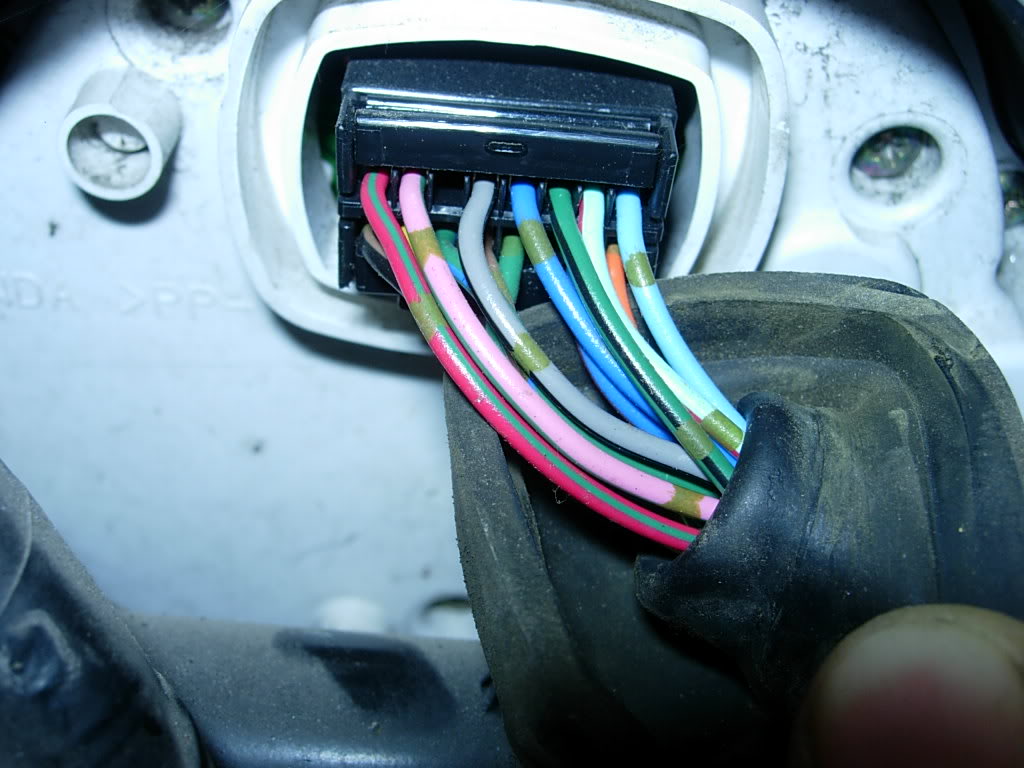
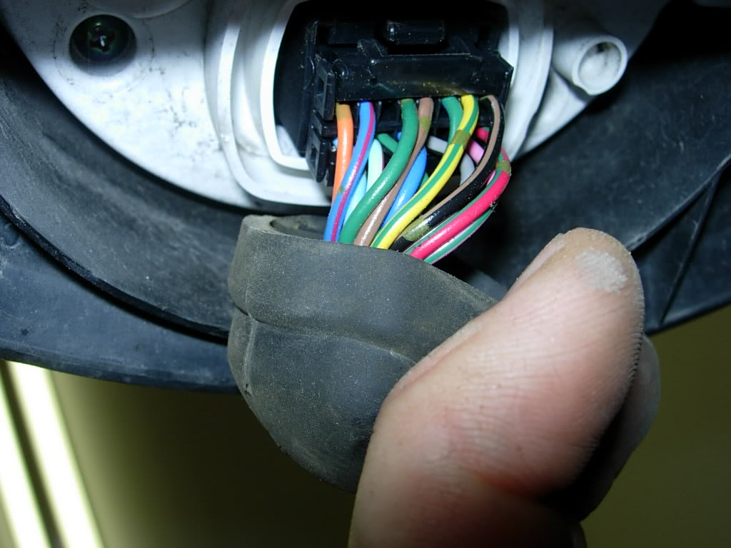
Can someone take a pic of the back of their 01+ unit with the harness plugged in as I want to be able to double check the wire colors.
Can someone take a pic of the back of their 01+ unit with the harness plugged in as I want to be able to double check the wire colors.
Junior Member
Squid
Joined: Aug 2008
Posts: 23
Just wanted to give you a heads up.. I put my 04 Fuel level Unit into a 1998 tank.. Bolts up correctly, but inside the tank the float hits the metal vent tubes that run inside.. I can either read from half tank to empty or full tank to half.. Depending on which side of the tubes I put the float on.. I am going to mess with it some more and try to bend the tubes out of the way somehow without breaking them.. Just a heads up for ya.. Might just be a Fubar'd Gas tank and you may not have this problem..
??
??
Thread Starter
Senior Member
SuperSport
Joined: Dec 2008
Posts: 507
From: Arizona
Well I purchased a fuel level sensor as well as the temperature sensor off an 04. They should be here by next weekend. I should also have the old speedo here within a few days so I can start hooking up the wires to the plug I will be making. Grizz should be getting me the detailed pics I need of the existing plug as I am unable to determine from the wiring diagrams what is where.
Thread Starter
Senior Member
SuperSport
Joined: Dec 2008
Posts: 507
From: Arizona
Got all the parts in. Still need the pinout of the harness off an 01+ of you can help. Offering $10 bucks for detailed photos.
So I just started by pulling the small wiring harness of a junker 98-00 stock speedo. I spent a few minutes and removed the old electrical tape, cutting off the ends, and cleaning up the sticky crap from the tape with some WD40.
So I just started by pulling the small wiring harness of a junker 98-00 stock speedo. I spent a few minutes and removed the old electrical tape, cutting off the ends, and cleaning up the sticky crap from the tape with some WD40.
Thread Starter
Senior Member
SuperSport
Joined: Dec 2008
Posts: 507
From: Arizona
***Still need the pinout of the harness off an 01+ if you can help. Offering $10 bucks for detailed photos. ***
Well had some time today so I figured I would start making the rest of the plug so once I get the pinout I can get this puppy together. I want to have a like stock plug that will latch into place. Finally found the type of plastic I was looking for. Ended up using some from a packing tape dispenser, seemed to be plenty strong yet flexibly for the latch. Just a few cuts, bends and some super glue and the plug is built. Good thing lazn showed me how to do the plastic welding last week, actually came in handy when the latch was getting a little weak and broke off from all the bending and tweaking. Latch feels strong and does not seem it will be going anywhere.
So the plug now sits firmly in place and even clicks into place when putting it in.
Oh yeah I ended up using exacto blade to remove the two tiny tabs or guides on the inside of the plug. Took 2 seconds and looks better than having to sand down the connector like i did last week.
Last edited by yruyur; Apr 24, 2009 at 02:21 PM.
Thread Starter
Senior Member
SuperSport
Joined: Dec 2008
Posts: 507
From: Arizona
So Lazn is over and we have figured out a majority of the pinouts by using an ohm meeter and comparing with the manual. We still need 5 so the 10 dollar reward is still available for anyone willing to go out to their bike and take a picture for me.
Thread Starter
Senior Member
SuperSport
Joined: Dec 2008
Posts: 507
From: Arizona
I removed all the factory splices(wow) they crimp them and use some hella hard shrink tubing. I soldered the old splice points and put shrink tubing on them. I cut the harness to length, crimped the molex connector contacts and soldered them for peace of mind.
As you can see in the pics the number of wires I removed.
As you can see in the pics the number of wires I removed.
Thread Starter
Senior Member
SuperSport
Joined: Dec 2008
Posts: 507
From: Arizona
Oh yeah and as you can see I created a banner ad for my signature begging for help from someone to supply some pics.
I may work on changing out the fuel level and temp sensor so that once I get the pinout I can just plop the gauges in.
I may work on changing out the fuel level and temp sensor so that once I get the pinout I can just plop the gauges in.
Thread Starter
Senior Member
SuperSport
Joined: Dec 2008
Posts: 507
From: Arizona
With the much appreciated help of Lazn we got some more stuff done tonight. We replaced the fuel level sensor and the temp sensor to the newer models.
After some searching around we found that the thermostat has 2 temps sensors on it. The larger one with the green plug has the same part number on it as the newer model. It appears this one does not need to be replaced as it sends the temp to the ecu.
The small headphone jack right next to it does need to be replaced with a newer model as it send the temp up to the gauges. We tested it according to the pre 01 instructions by putting it in hot water and testing it with an ohm meter, it definitely does not register the same. The part number we could read on them were completely different even though Ron Ayers has the part numbers listed as the same on their site.
The fuel sensors are definetely different. The pre 01 unit is the one with the yellow wire and little sensor at the end of the arm. On this unit the arm does not move but just senses gas touching or not touching it for the low fuel light. The 01+ unit has the black float at the end of the arm and the arm moves like in a toilet.
The fuel sensor was pretty easy except for the O ring that seals the sending unit to the tank seems to be a little larger on the new model(leaked when we put the pre 01 O ring on). We needed to figure out what direction the float went as well. We decide the arm or the float needed to be pointed toward the seat.
The base plate the sending unit mounts to has the wires attached in two different spots on the different years. The pre 01 has the wires coming out on the left side while the 01+ have them coming out the right side. As you can see from the pic both the wiring harness are pointed in the same direction but the floats are pointed in the opposite directions. I hope we put it in the tank the right direction.
We were sure not to hook any of the wires up yet as we didnt want to cook the old gauges some how. Now that we have everything in place it looks like I just need to pinout on the harness and Ill be able to install the gauges.

Thread Starter
Senior Member
SuperSport
Joined: Dec 2008
Posts: 507
From: Arizona
Woohooo you are awesome! Your PM you sent me says you dont want the $10 bucks but I am more than willing to PayPal it to you as you took the time to take the pics.
Now I want to get started on this......but I have to go to work
Now I want to get started on this......but I have to go to work
Thread Starter
Senior Member
SuperSport
Joined: Dec 2008
Posts: 507
From: Arizona
So the first thing I noticed in the pic is there is a new color on the 01+ than on the older models. Serves the same purpose but what used to be the brown/black is now grey/black which goes to the fuel sensor. Still putting the plug together had to take a nap. Ill be back.


