New lights
 11-04-2014, 01:46 PM
#1
Administrator
MotoGP
Thread Starter

Join Date: Apr 2006
Location: Kempner, TX
Posts: 4,402

New lights
While I wait on my new rear brake caliper mount
Figured I'd install my new lights.
Bought the TRS projector kit with the upgrade bulb in 4500k from the retrofit source $150
New euro OEM honda switch assembly pn 35020-mbb-640 $41
And an hour of my time tonight to put it together
I know
I know pics or it never happened
Film at eleven
Figured I'd install my new lights.
Bought the TRS projector kit with the upgrade bulb in 4500k from the retrofit source $150
New euro OEM honda switch assembly pn 35020-mbb-640 $41
And an hour of my time tonight to put it together
I know
I know pics or it never happened
Film at eleven
Last edited by E.Marquez; 11-04-2014 at 05:11 PM.


 11-04-2014, 08:20 PM
#6
Senior Member
Back Marker

Join Date: Feb 2014
Posts: 148
Ohhhh man, REALLY want that headlight switch, always wanted the pass toggle and a better solution to keeping the lights turned off during startup. I have a TRS projector as well, so this might be ordered soon. It's plug and play I assume?
11-05-2014, 03:26 AM
#8
Administrator
MotoGP
Thread Starter
Join Date: Apr 2006
Location: Kempner, TX
Posts: 4,402
Hid bulbs and ballast Do not last long with continued low voltage dips and refire attempts
The euro assembly also has the flash to pass function. It just momentarily flash the high beam
And at $41 I get a nice shiney new switch assembly
Last edited by E.Marquez; 11-05-2014 at 03:29 AM.
11-05-2014, 09:05 AM
#9
Senior Member
MotoGP

Join Date: Jul 2007
Location: NYC
Posts: 5,033
Plus you get a new turn sig switch that will work in colder temps if that applies. I installed a headlight cutout switch for when I need it. Be careful to not forget and ride with it off. Raises danger level considerably.


 11-05-2014, 02:18 PM
#13
Administrator
MotoGP
Thread Starter
Join Date: Apr 2006
Location: Kempner, TX
Posts: 4,402
Excited?
Naw.. just a simple solution to adding a on/off switch to the headlight for start up... Which in my opinion, is only necessary due to the bike being an old design not set up for HID.s
Running without a headlight on is not the brightest(pun intended) ideas.
Naw.. just a simple solution to adding a on/off switch to the headlight for start up... Which in my opinion, is only necessary due to the bike being an old design not set up for HID.s
Running without a headlight on is not the brightest(pun intended) ideas.
11-05-2014, 02:21 PM
#14
Administrator
MotoGP
Thread Starter
Join Date: Apr 2006
Location: Kempner, TX
Posts: 4,402
 11-05-2014, 04:42 PM
#16
Member
Squid
Join Date: Apr 2011
Location: Canada
Posts: 85
The European Switch is almost plug and play into the US wiring loom. If I remember correctly one plug is direct fit the other needs a few wires rearranged to the correct location. And a few wires won't have homes. We worked it out Here. I can always run out and double check if needed.
And the off position is great for the HID setup, and the passing switch as well for that matter
And the off position is great for the HID setup, and the passing switch as well for that matter
11-05-2014, 06:19 PM
#17
Administrator
MotoGP
Thread Starter
Join Date: Apr 2006
Location: Kempner, TX
Posts: 4,402
The European Switch is almost plug and play into the US wiring loom. If I remember correctly one plug is direct fit the other needs a few wires rearranged to the correct location. And a few wires won't have homes. We worked it out Here. I can always run out and double check if needed.
And the off position is great for the HID setup, and the passing switch as well for that matter
And the off position is great for the HID setup, and the passing switch as well for that matter
Thanks
Im using your post as my plan for the swap..
Think its under control, but darn sure will ask questions of you if I get stuck
11-10-2014, 12:41 PM
#18
Administrator
MotoGP
Thread Starter
Join Date: Apr 2006
Location: Kempner, TX
Posts: 4,402
The European Switch is almost plug and play into the US wiring loom. If I remember correctly one plug is direct fit the other needs a few wires rearranged to the correct location. And a few wires won't have homes. We worked it out Here. I can always run out and double check if needed.
And the off position is great for the HID setup, and the passing switch as well for that matter
And the off position is great for the HID setup, and the passing switch as well for that matter
1st issue, not only do the wires need to be adjusted.. one of the two plugs is completely different.. and will need to be changed as well.
Old switch plugs on left, new Euro switch plugs on right


So need to figure that stuff out first.
11-10-2014, 02:42 PM
#19
Administrator
MotoGP
Thread Starter
Join Date: Apr 2006
Location: Kempner, TX
Posts: 4,402
What we have discovered is, while there may be some non Euro models that are "mostly plug and play" the Made June 1997 Non CA VTR1000F I have in front of me, is anything but.
1 Plug housing does not physically mate
Almost none of the pins are in the same location US to Euro.
And of course functionality of one switch assembly and wiring harness is much different than the other.
Let the games begin
1 Plug housing does not physically mate
Almost none of the pins are in the same location US to Euro.
And of course functionality of one switch assembly and wiring harness is much different than the other.
Let the games begin
11-10-2014, 03:58 PM
#20
Senior Member
SuperBike

Join Date: Sep 2010
Location: Bisbee, AZ
Posts: 1,873
11-10-2014, 04:13 PM
#21
Senior Member
SuperBike
Join Date: Sep 2010
Location: Bisbee, AZ
Posts: 1,873
Have been following this swap with interest.
Have you considered picking out the terminals and installing into a matching connector? I thing what is being used is this Motorcycle 2.8mm - 110 Connector and Terminals
I purchased a bunch of parts from them and was very satisfied.
Just a thought for you to ponder.
Have you considered picking out the terminals and installing into a matching connector? I thing what is being used is this Motorcycle 2.8mm - 110 Connector and Terminals
I purchased a bunch of parts from them and was very satisfied.
Just a thought for you to ponder.
11-10-2014, 04:14 PM
#22
Senior Member
SuperBike
Join Date: Sep 2010
Location: Bisbee, AZ
Posts: 1,873
Have been following this swap with interest.
Have you considered picking out the terminals and installing into a matching connector? I think this is the connecto being used: Motorcycle 2.8mm - 110 Connector and Terminals
I purchased a bunch of parts from them and was very satisfied.
Just a thought for you to ponder.
Have you considered picking out the terminals and installing into a matching connector? I think this is the connecto being used: Motorcycle 2.8mm - 110 Connector and Terminals
I purchased a bunch of parts from them and was very satisfied.
Just a thought for you to ponder.
11-10-2014, 04:52 PM
#23
Administrator
MotoGP
Thread Starter
Join Date: Apr 2006
Location: Kempner, TX
Posts: 4,402
Have been following this swap with interest.
Have you considered picking out the terminals and installing into a matching connector? I thing what is being used is this Motorcycle 2.8mm - 110 Connector and Terminals
I purchased a bunch of parts from them and was very satisfied.
Just a thought for you to ponder.
Have you considered picking out the terminals and installing into a matching connector? I thing what is being used is this Motorcycle 2.8mm - 110 Connector and Terminals
I purchased a bunch of parts from them and was very satisfied.
Just a thought for you to ponder.
1st mapped each pin location / wire color / function for both US (old) Euro (new) switch assembly.
Traced the mating pin on the harness plug and confirmed what It looked like the switch did, was connected to the correct electrical component.
Took pictures of all 6 plugs from all sides so it could be referenced later.
Pulled pins from the old plugs so I had the plug shell.
Then one a a time removed pins form the new switch plugs and placed it in the correct location in the old matching plug.
30 min later, I have a working Euro switch assembly wired to a US bike. All functions work as desired.
 11-10-2014, 06:04 PM
#25
Administrator
MotoGP
Thread Starter
Join Date: Apr 2006
Location: Kempner, TX
Posts: 4,402
I also chose to wire the third light to the intended brown wire in the Euro switch . There is a open spot in the US large green 9P connector shell, but I was out of that type of pins tonight, so I used an OEM style bullet connector.
11-10-2014, 07:35 PM
#26
Administrator
MotoGP
Thread Starter
Join Date: Apr 2006
Location: Kempner, TX
Posts: 4,402
Here is the pin out I used to set EURO left side switch assembly pins(wires) in to the US switch assembly connectors
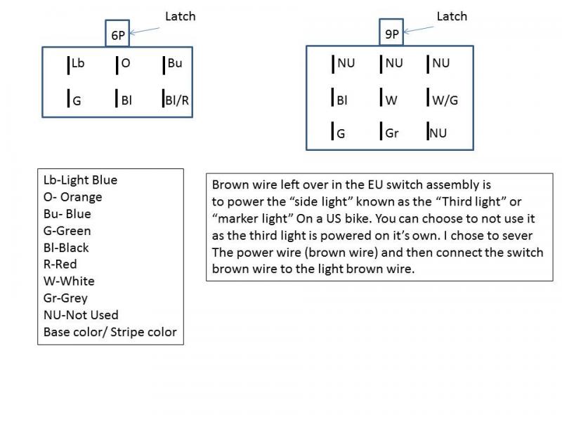
Pins can be released from the connector housing by using a very small flat blade screw driver.. think Micro precision . A small nail or stiff wire ground flat works as well.
Pins can be released from the connector housing by using a very small flat blade screw driver.. think Micro precision . A small nail or stiff wire ground flat works as well.
11-11-2014, 12:05 PM
#27
Administrator
MotoGP
Thread Starter
Join Date: Apr 2006
Location: Kempner, TX
Posts: 4,402
On to the projector install... hey this should only take a few minutes, it's plug and play like the switch...right?.....RIGHT?
Errrr, No not even close.
So lets get busy
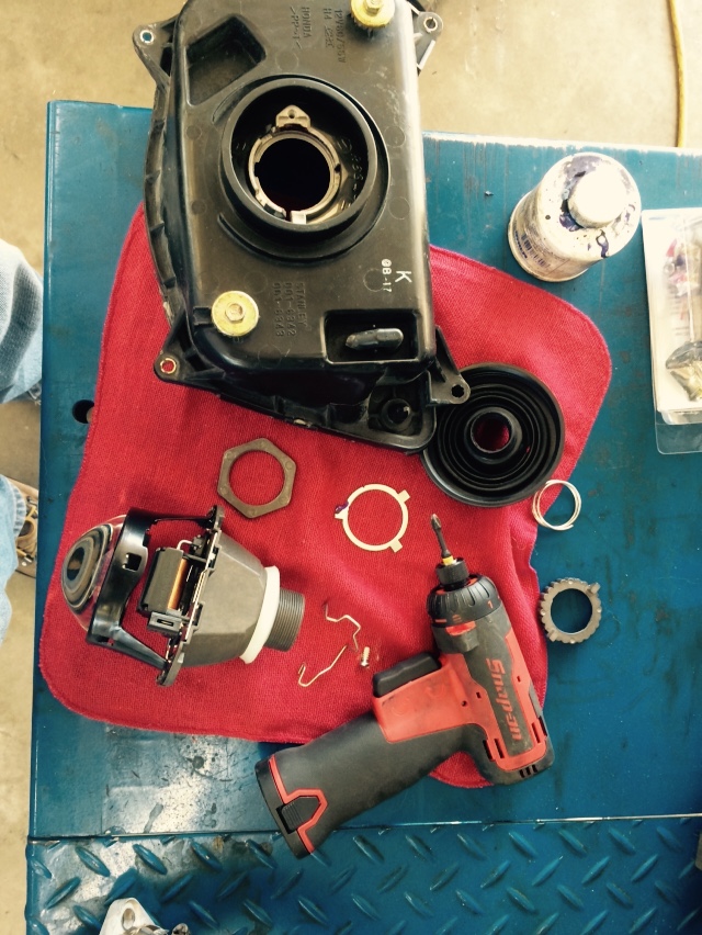
Bake open the light, 265 for 7 min did it for me.. gently pry the locking tabs open when separating the housing and it comes right apart.
Keep the mastic clean or it will not reseal.
Like others have noted, the projector will set at an angle if not corrected.
Some grind the tabs, others mod the housing.. I did both... but first the indexing ring.
Remove the tab that indexes the light
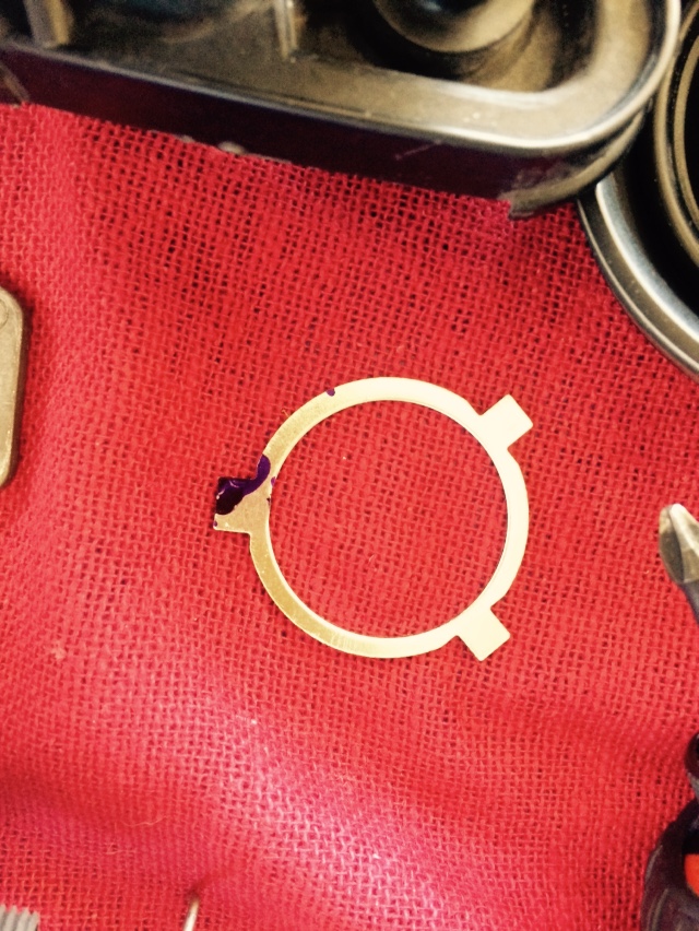
install in housing, mark needed location weld on a new tab, shape to fit with files...
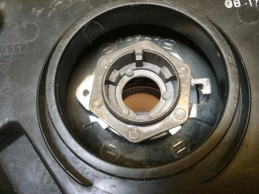
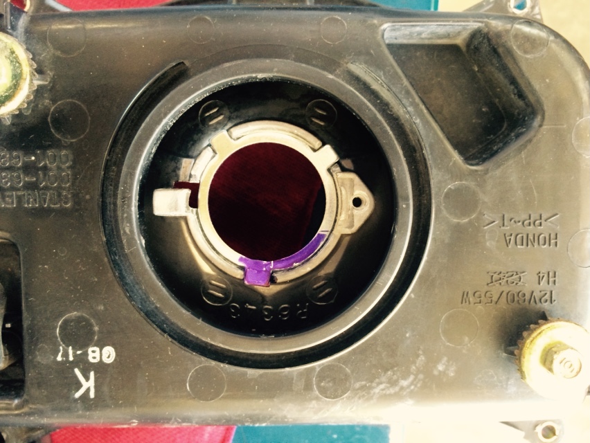
Next two issues.. projector does not protrude through the housing far enough to leave room for the bulb lock ring. AND the projector lock ring will only touch the two high points on the housing where the H4 bulb wire lock fits..
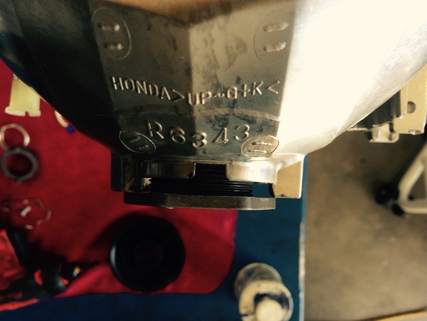
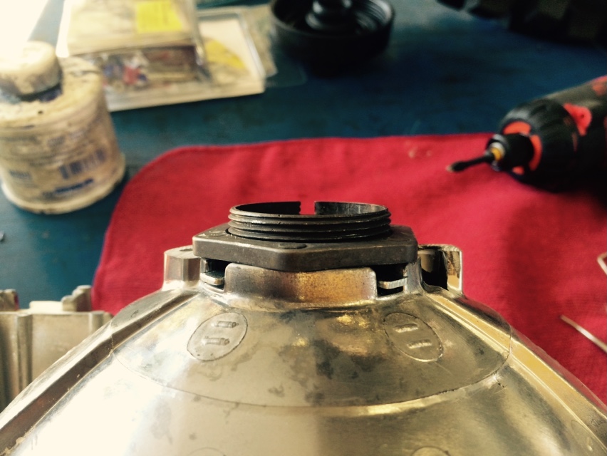
Trimming the housing so the lock ring mating surface is flat was my decision.. I know have 360 seating . And with those two protrusion cut off, the lock ring screws down nicely leaving 5mm of projector remaining for the bulb lock ring.
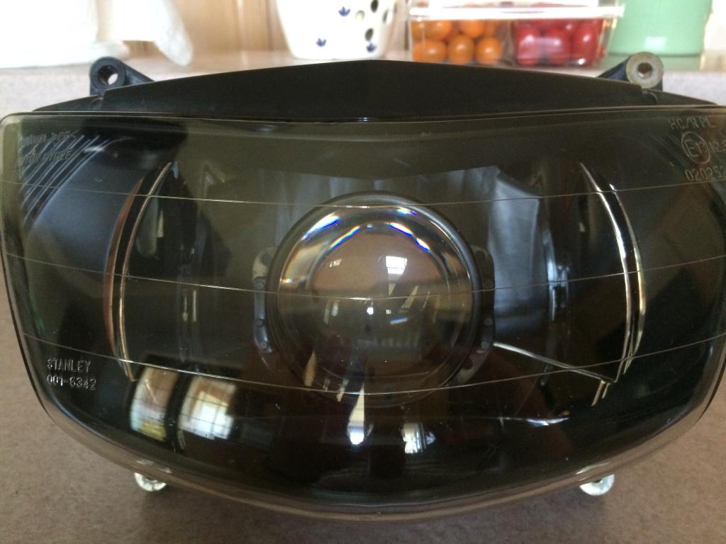
All fixed
So projector mounted, headlight re sealed.. on to the routing, mounting, modifying the harness and getting it wired up.
Errrr, No not even close.
So lets get busy

Bake open the light, 265 for 7 min did it for me.. gently pry the locking tabs open when separating the housing and it comes right apart.
Keep the mastic clean or it will not reseal.
Like others have noted, the projector will set at an angle if not corrected.
Some grind the tabs, others mod the housing.. I did both... but first the indexing ring.
Remove the tab that indexes the light


install in housing, mark needed location weld on a new tab, shape to fit with files...


Next two issues.. projector does not protrude through the housing far enough to leave room for the bulb lock ring. AND the projector lock ring will only touch the two high points on the housing where the H4 bulb wire lock fits..

Trimming the housing so the lock ring mating surface is flat was my decision.. I know have 360 seating . And with those two protrusion cut off, the lock ring screws down nicely leaving 5mm of projector remaining for the bulb lock ring.
All fixed

So projector mounted, headlight re sealed.. on to the routing, mounting, modifying the harness and getting it wired up.
11-11-2014, 01:23 PM
#28
Administrator
MotoGP
Thread Starter
Join Date: Apr 2006
Location: Kempner, TX
Posts: 4,402
Instructions.. we don't need no stinking instructions...
So that "HighBeam" out put,,,, ya it plugs into the projector..... not just a trigger source.
I wrongly assumed (assumed because there are NO real instructions for this thing) that the two pin female connector on the projector was for the optional Halo light..WRONG
Warming up the oven again time Meow
11-11-2014, 06:08 PM
#29
Administrator
MotoGP
Thread Starter
Join Date: Apr 2006
Location: Kempner, TX
Posts: 4,402
Self induced mistake number 2...
Im a product of my environment.. When I travel .... I would have to drive in LEFT HAND DRIVE countries.. because they drive on the LEFT HAND side of the road...
TRS defines left and right hand drive as where the driver sits ...like you would in the US for a special permitted right hand drive vehicle (postal or import)
So I screwed up and ordered a RHD lens...... On the bright side, TRS was GREAT in setting up the exchange at no cost. I elected to have the correct projector shipped immediately and return the wrong one later.. So I paid a "core" and shipping now and will be refunded once the other is received.
Lesson is... LHD/RHD is based on DRIVER position, not what side of the road you drive on.
Last edited by E.Marquez; 09-06-2016 at 06:40 AM.
11-11-2014, 07:08 PM
#30
Administrator
MotoGP
Thread Starter
Join Date: Apr 2006
Location: Kempner, TX
Posts: 4,402
Next issue... the positive wire fuse holder which is an open non sealed design, and the placement on the OEM cable put it in an inaccessible position behind the frame.
So I cut out the OEM fuse holder , soldered some marine grade (tinned) 12ga wire, and a weather sealed Mini ATO fuse holder
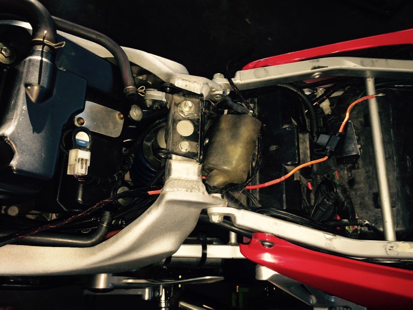
You can see where the black braided covering ends... that plus 1 in is where the open unsealed type full size ATO fuse holder would have been... Good enough no doubt... but I wanted it to be a sealed, mini ATO so it matched all other fuse types, and in a more accessible location..
All temporary anyway as I'm adding a FZ1 fuse box as soon as it comes in. I have one sitting on the bench for a customer who is not looking to get his bike back for two more weeks...so tempting to use that one now and wait on the ordered one.... but thats just wrong..and with my luck the ordered one will get lost in shipping.
http://www.fuzeblocks.com/


If you have not heard about the FZ1 fuse block...its a neat deal. ATO mini fuses, compact overall, each circuit is selectable as switched or no based on fuse position.
One connection to the battery ridding the battery of those multiple terminals and several relays if you have several accessories wired in.
I've installed and wired 4 of these now, been in service for many months no issues. I learned of this product on a pair of Adventure bikes I came to work on http://www.twtex.com/forums/showthread.php?t=90264
They lasted almost a year on the road from canada to south america and back
So I cut out the OEM fuse holder , soldered some marine grade (tinned) 12ga wire, and a weather sealed Mini ATO fuse holder

You can see where the black braided covering ends... that plus 1 in is where the open unsealed type full size ATO fuse holder would have been... Good enough no doubt... but I wanted it to be a sealed, mini ATO so it matched all other fuse types, and in a more accessible location..
All temporary anyway as I'm adding a FZ1 fuse box as soon as it comes in. I have one sitting on the bench for a customer who is not looking to get his bike back for two more weeks...so tempting to use that one now and wait on the ordered one.... but thats just wrong..and with my luck the ordered one will get lost in shipping.
http://www.fuzeblocks.com/
If you have not heard about the FZ1 fuse block...its a neat deal. ATO mini fuses, compact overall, each circuit is selectable as switched or no based on fuse position.
One connection to the battery ridding the battery of those multiple terminals and several relays if you have several accessories wired in.
I've installed and wired 4 of these now, been in service for many months no issues. I learned of this product on a pair of Adventure bikes I came to work on http://www.twtex.com/forums/showthread.php?t=90264
They lasted almost a year on the road from canada to south america and back
Last edited by E.Marquez; 09-14-2018 at 06:00 AM. Reason: pic added


