R1/R6 Regulator/Rectifier Swap
 12-22-2011, 09:11 AM
#121
Junior Member
Squid

Join Date: Dec 2011
Location: Staffordshire, England
Posts: 5

Saige, many thanks for your quick reply. That's a relief 
My winter project includes manual CCT mod, the R/R mod, full service and I should be good to go.
My winter project includes manual CCT mod, the R/R mod, full service and I should be good to go.
Last edited by Sandyback; 12-22-2011 at 12:58 PM.
 08-07-2012, 02:25 PM
#123
Senior Member
SuperSport

Join Date: Jul 2012
Location: Santa Fe, New Mexico
Posts: 582
OK, I'm ready to do the swap, but I have a question: is there a way to tell pos & neg on the R1 RR and does it matter what order the yellow wires plug in? I know the pix show everything wired up but I'm wanting to be certain about wire placement so I don't inflict damage to my bike.
08-07-2012, 04:14 PM
#125
Senior Member
SuperSport
Join Date: Jul 2012
Location: Santa Fe, New Mexico
Posts: 582
Its been discussed but maybe its because your fitting a more modern unit R/R. 
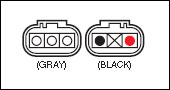
As far as i can see from a wiring diagram, the grey socket houses 3 connections for the pulse/pickup wires and the black socket houses 2 connections for the negative (+) and positive (-).
The diagram below will show which order the (+) and (-) fits.
As far as i can see from a wiring diagram, the grey socket houses 3 connections for the pulse/pickup wires and the black socket houses 2 connections for the negative (+) and positive (-).
The diagram below will show which order the (+) and (-) fits.
https://www.superhawkforum.com/forum...er-swap-14380/
This part was pricy and I don't want to blow it up or my battery and other parts. I want to be certain I'm connecting everything right!
08-07-2012, 04:20 PM
#126
Senior Member
SuperSport
Join Date: Jul 2012
Location: Santa Fe, New Mexico
Posts: 582
OK, now I feel totally stoooopid. I posted before I saw your reply, 7more7.
Thanks for replying. It seems to reason that I would fit the wires same as oem connections, red to inside, but I want to be sure. BTW, what would be the result of reversing the power wires? (I have to plead confusion from my earlier encounter with a deer).
Thanks for replying. It seems to reason that I would fit the wires same as oem connections, red to inside, but I want to be sure. BTW, what would be the result of reversing the power wires? (I have to plead confusion from my earlier encounter with a deer).
08-09-2012, 09:11 AM
#127
Out of my mind, back in 5
MotoGP

Join Date: Nov 2006
Location: Skurup, Sweden
Posts: 6,109
OK, now I feel totally stoooopid. I posted before I saw your reply, 7more7.
Thanks for replying. It seems to reason that I would fit the wires same as oem connections, red to inside, but I want to be sure. BTW, what would be the result of reversing the power wires? (I have to plead confusion from my earlier encounter with a deer).
Thanks for replying. It seems to reason that I would fit the wires same as oem connections, red to inside, but I want to be sure. BTW, what would be the result of reversing the power wires? (I have to plead confusion from my earlier encounter with a deer).
08-09-2012, 11:26 AM
#128
Moderator
MotoGP

Join Date: Jul 2007
Location: Gettysburg, Pa
Posts: 5,071
Its been discussed but maybe its because your fitting a more modern unit R/R.
As far as i can see from a wiring diagram, the grey socket houses 3 connections for the pulse/pickup wires and the black socket houses 2 connections for the negative (+) and positive (-).
The diagram below will show which order the (+) and (-) fits.
As far as i can see from a wiring diagram, the grey socket houses 3 connections for the pulse/pickup wires and the black socket houses 2 connections for the negative (+) and positive (-).
The diagram below will show which order the (+) and (-) fits.
Guess I should edit out that diagram to end confusion, yes?
Last edited by Wolverine; 10-21-2014 at 06:59 AM.
08-10-2012, 09:01 AM
#129
Out of my mind, back in 5
MotoGP
Join Date: Nov 2006
Location: Skurup, Sweden
Posts: 6,109

Actually, both are correct... Albeit the first one is confusing, it's still correct... One is looking at the R/R, the other at the plugs...
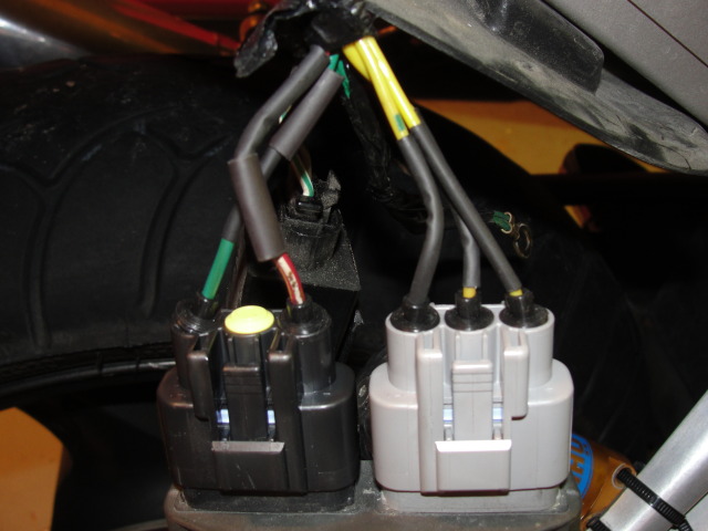
Have a look at the little image and note the notches on the connectors, and then look at the photo below...
If you move the two connectors in the opposite orientation, ie swap them over, you get a better representation, still correct, but less confusing, as it then becomes more obvious that it's the connectors we are looking at...
08-10-2012, 09:03 AM
#130
Out of my mind, back in 5
MotoGP
Join Date: Nov 2006
Location: Skurup, Sweden
Posts: 6,109
Or make it dummy proof... Black connector, positive wire on the end with double notches/cutouts... Negative wire on the end with a single notch/cutout...
Instead of "inside/outside" which only works if you look at the R/R, and not the wiring...
Instead of "inside/outside" which only works if you look at the R/R, and not the wiring...
08-10-2012, 09:24 AM
#131
Senior Member
MotoGP

Join Date: Jul 2010
Location: Phoenix, AZ
Posts: 3,869
I think we need a clever acronym about wire color placement on the R/R. Or maybe a song.
Righty tighty, lefty loosy!
Stalactites hang tightly from the ceiling. Stalagmites MIGHT... but they don't.
^ Something along those lines.
Righty tighty, lefty loosy!
Stalactites hang tightly from the ceiling. Stalagmites MIGHT... but they don't.
^ Something along those lines.
08-16-2012, 01:14 PM
#132
Joe Fo Sho
Squid
Join Date: May 2012
Location: Cleveland,Oh
Posts: 50
No earth wire present?
I recently did this mod. Everytjing seems to be fine but my volt meter seems to be reading 15.1-15.6 volts when i check it after a ride with engine on? Is this normal? If not, in the thread it showz a green earth wire attatched to mounting bolt. I dont remember a any wire being attatchedto my stocker. Does the 03 have the earth wire as well? if so and its not attatched could this be my problem? Thanks for any info guys
08-16-2012, 01:42 PM
#133
Out of my mind, back in 5
MotoGP
Join Date: Nov 2006
Location: Skurup, Sweden
Posts: 6,109
I recently did this mod. Everytjing seems to be fine but my volt meter seems to be reading 15.1-15.6 volts when i check it after a ride with engine on? Is this normal? If not, in the thread it showz a green earth wire attatched to mounting bolt. I dont remember a any wire being attatchedto my stocker. Does the 03 have the earth wire as well? if so and its not attatched could this be my problem? Thanks for any info guys
And yes, there should be a green wire that grounds to the frame close to the R/R on all years, but it's defiently not the entire problem...
09-04-2014, 06:43 AM
#135
Senior Member
Back Marker

Join Date: Nov 2010
Location: philadelphia
Posts: 139
So if an ebay R1 RR is roughly $40 and the connectors are roughly $25 and that involves cutting wires etc. is there any reason why this wouldnt be a good option? I understand that is essentially an additionaly $30, but... it should be every bit as good right? 1998 Honda VTR1000 SuperHawkStreet Bike OEM Style Honda Rectifier-Regulator Aftermarket Parts
I am just trying to get a better understanding.
Thanks
Craig
I am just trying to get a better understanding.
Thanks
Craig
09-04-2014, 08:14 AM
#136
Senior Member
MotoGP
Join Date: Jul 2010
Location: Phoenix, AZ
Posts: 3,869
Nope, definitely not as good. Even the older r6 regulator isn't the best option now because it's a shunt based one as well (just with huge fins). There doesn't exist a plug and play option that is optimal. It's about the technology inside of the unit. This thread will help understand more:
https://www.superhawkforum.com/forum...why-how-25117/
https://www.superhawkforum.com/forum...why-how-25117/
09-04-2014, 12:26 PM
#137
Senior Member
Back Marker
Join Date: Nov 2010
Location: philadelphia
Posts: 139
Thanks for the info- i went with the r1 rr and the connector kit from eager beaver or whatever that site is. and.. i saved some monies as well- now- i just have to sit and wait for everything to show up- and stare at my superhawk - stranded in the garage.
Craig
Craig
09-04-2014, 05:40 PM
#138
Senior Member
SuperBike
SuperBike

Join Date: Feb 2013
Posts: 1,509
Question: the diagram above should be the same for the 04-05 zx10 regulator/rectifier i picked up, correct? Part number FH010BA.
It is low profile with cooling fins, and has a 3 pin gray connector, and a 2 pin black connector.
Thanks!
James
It is low profile with cooling fins, and has a 3 pin gray connector, and a 2 pin black connector.
Thanks!
James
10-20-2014, 07:14 PM
#140
not a
Back Marker

Join Date: Aug 2012
Location: Anaheim, CA
Posts: 101
Its been discussed but maybe its because your fitting a more modern unit R/R.
As far as i can see from a wiring diagram, the grey socket houses 3 connections for the pulse/pickup wires and the black socket houses 2 connections for the negative (+) and positive (-).
The diagram below will show which order the (+) and (-) fits.
As far as i can see from a wiring diagram, the grey socket houses 3 connections for the pulse/pickup wires and the black socket houses 2 connections for the negative (+) and positive (-).
The diagram below will show which order the (+) and (-) fits.
10-21-2014, 06:53 AM
#141
Moderator
MotoGP
Join Date: Jul 2007
Location: Gettysburg, Pa
Posts: 5,071

Note position of red wire and green in the black plug.
Last edited by Wolverine; 10-21-2014 at 07:26 AM.
10-21-2014, 08:57 PM
#142
not a
Back Marker
Join Date: Aug 2012
Location: Anaheim, CA
Posts: 101
So the green wire (while plugged in) is on the outside of the r/r... Right? Also are they supposed to get some what hot pretty quick? Thanks i just did mine.

 05-29-2018, 03:01 PM
#144
Administrator
MotoGP

Join Date: Apr 2006
Location: Kempner, TX
Posts: 4,402
Its not an RR I have data on, so im not sure what the control circuit is, or wither it is thyristors, diodes, and MOS FETs, no idea what the rated capacity is, or if it is switched or shunt design.
Also don't know if they are prone to failure, or known to be robust when used on a VTR. so its a big if over all....
FH020AA / FH012AA is common, cheap used, and decent priced new, known to work well on this bike and known to be trouble free over all on all bikes it came on..they just are not known to fail... There is a lot written on the install of one making it pain free to do.
Folks have installed all manner of RRs on this bike, some work, some fail... BUT the FH022BA is an unknown, so
Last edited by E.Marquez; 05-29-2018 at 03:14 PM.
05-30-2018, 05:40 AM
#146
Administrator
MotoGP
Join Date: Apr 2006
Location: Kempner, TX
Posts: 4,402
Ive bought and used dozens of take off FH020AA / FH012AA. RR's Tested them all before use and all fine, tested after install or sale, all fine, and not a single one has been reported back as failed in a lot of years now. So long as it test and works fine on install, the install is done correctly I think there is no issue with a used FH020AA / FH012AA. Quality of the install is key
07-21-2018, 11:26 AM
#149
Junior Member
Squid

Join Date: Jun 2018
Location: Derby, Kansas
Posts: 22
Then there's the MCCTs......
07-21-2018, 04:17 PM
#150
Moderator
MotoGP
Join Date: Jul 2007
Location: Gettysburg, Pa
Posts: 5,071


